1727
10µm isotropic voxels acquired with a CMOS-based planar microcoil at 14.1T: Preliminary results1High-Field MR Center, Max Planck Institute for Biological Cybernetics, Tübingen, Germany, 2Graduate Training Centre of Neuroscience, IMPRS for Cognitive and Systems Neuroscience, University of Tübingen, Tübingen, Germany, 3Institute of Microelectronics, University of Ulm, Ulm, Germany, 4Institute of Theory of Electrical Engineering, University of Stuttgart, Stuttgart, Germany, 5Department for Biomedical Magnetic Resonance, University of Tübingen, Tübingen, Germany
Synopsis
The quest for high resolution MR have push the technology to miniaturization. Thus, microcoils have been used for imaging with very high resolution. Here, we have designed and constructed a fully integrated CMOS NMR transceiver containing an on-chip microcoil, integrated amplifiers and demodulator for the high-frequency MR signal. In the present work, the initial microimaging results of this fully-integrated NMR transceiver in a 14.1 T animal scanner are presented. The on-chip microcoil allows imaging with a spatial resolution down to 10 µm with an SNR of 64 and with an improvement in SNR/volume ratio of 150 compared to a 10 mm surface coil.
INTRODUCTION
The sensitivity of a coil increases with decreasing size, and thus microcoils have been used for imaging with very high resolution or spectroscopic applications1,2,3,4. However, with decreasing coil size the cables lead to increased noise, signal loss and possible coupling to other sources. To mitigate these effects, we have designed and constructed a fully-integrated CMOS5 NMR transceivers containing an on-chip microcoil, integrated amplifiers and demodulation of the high-frequency MR signal. This significantly reduces the complexity of the required off-chip electronics and minimizes losses in the connecting cables. Here, we present preliminary imaging results using the active CMOS microcoils towards in-vivo highly-localized imaging in an animal scanner.METHODS
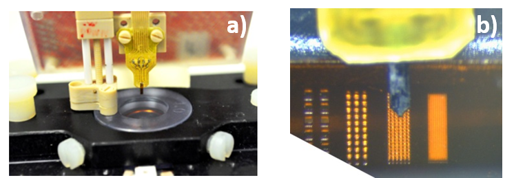
The signal is acquired with a fully-integrated NMR transceiver including an on-chip broadband MR-microcoil (300µm-diameter double-spiral coil) on a silicon substrate. The NMR transceiver chip is directly bonded to a small supporting PCB (Fig.1). A 3 cm long flexible cable connects the probe head to a signal-conditioning PCB for amplification. The processed signal is then sent to a National Instruments data acquisition card (NI PXIe-6368, National Instruments, Austin, TX, USA) outside the scanner room for A/D conversion and digital signal processing, similar to Ref. 3-6. The microcoil can be used as transceiver (TX/RX) or in receive-only (RX-only)4,5 mode in combination with the scanners RF excitation pulse. The coil with the amplifier board (Fig.1) was placed inside a Bruker Biospec spectrometer (Bruker BioSpin GmbH, Ettlingen, Germany) interfaced to a 14.1-T/26-cm horizontal magnet (Magnex Scientific, Abingdon, Oxfordshire, UK). The tip of the chip containing the microcoil was inserted into doped water (10mM of Gd) – Fig.1. A large 10 mm single loop surface coil positioned below the chip was used to confirm the position of the chip in the sample. Additionally, a laser cut grid on a polyimidefoil was imaged as benchmark experiments with known structures (Fig1.b)7. In all the experiments, the microcoil (attached to the holding PCB) is positioned inside the sample by a micro driver.For imaging with the microcoil, a 3D GRE sequence was used. The microcoil was used for both transmitting and receiving, controlled by trigger pulses from the scanner for synchronization with the imaging gradients. For excitation, a hard pulse of 10µs length is used, which gave the maximum signal for the GRE sequence. A total scan time of 13 min and 39 s was required for a voxel size of 13 µm isotropic with TR/TE=50/4.77 ms, single acquisition, FOV=6.66x1.66x1.66 mm3, Matrix size=512x128x128. For images with a further improved resolution of 10 µm isotropic, a similar 3D GRE sequence was used: scan time=13min 39s, TR/TE=50/5.77 ms, single acquisition, FOV=5.12x1.28x1.28 mm3, Matrix size=512x128x128. For these measurements, the shim was carefully adjusted manually, requiring a strong compensation in the X direction (10kHz/cm) in order to get a water-peak linewidth of ~30Hz.
RESULTS
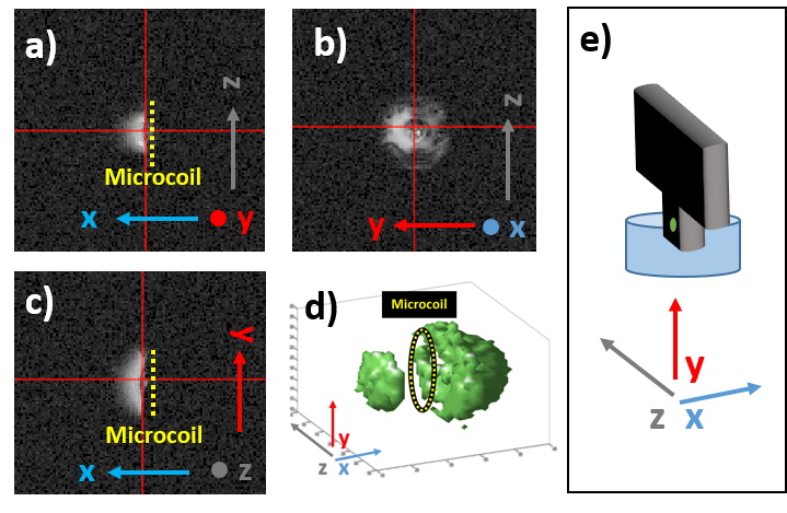
The estimated sensitive
volume of the microcoil was approximately 5nl (nanoliters) - Fig.2. Due the
intrinsic inhomogeneities of spiral coils near their surface (Fig.2.b),
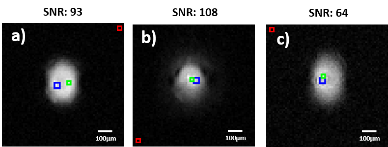
homogeneous slices ~50µm away from the center were selected to calculate the
SNR for the TX/RX and RX-only configuration at 13µm isotropic resolution for
comparison (Fig.3.a and .b). For both modalities, the optimum flip angle was
used. The 10 µm isotropic resolution images were acquired in TX/RX
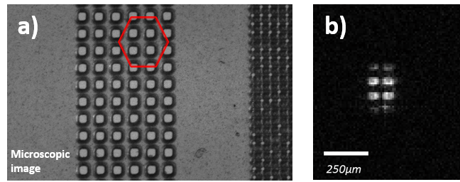
configuration (Fig.3.c). Finally, a known structure (grid pattern on a
polyimide foil) was imaged and is presented in Fig. 4.DISCUSSION
Fig. 3 and 4 demonstrate the capability of fully-integrated CMOS microcoil to image very small volumes (~5nl). The system is capable of imaging at a very high resolution (up to 10 µm isotropic) in a single scan with an acceptable SNR. Soft tissue imaging is under progress. Fig. 4b presents the capability of the microcoil to distinguish structures at very high spatial resolution, by clearly depicting the 50 µm-wide holes in the polyimide foil. The same high-spatial-resolution sequences were acquired on the 10 mm single-loop surface coil were almost no signal was acquired (not shown here). Therefore, in separate experiments the SNR improvement was calculated from simple FIDs, showing a gain of 150 times with the microcoil over the 10 mm coil in the SNR/volume ratio.CONCLUSION
We have demonstrated the
ability to perform imaging with a fully-integrated CMOS transceiver with
on-chip microcoil with a sensitive volume of approximately 5 nl. Imaging with
resolutions up to 10µm isotropic was achieved in a single scan. In-vivo
experiments are under progress. Additionally, we are investigating the
possibility to improve the field homogeneity around the micro coil (ΔB0=~200Hz) by changing its orientation or by coating it with a
susceptibility-compensating substrate8.Acknowledgements
No acknowledgement found.References
1. Weiger M. et al. NMR microscopy with isotropic resolution of 3.0 µm using dedicated hardware and optimized methods. Concepts Magn Reson Part B Magn Reson Eng.2008;33B(2):84-93.
2. Weber H. et al. Microcoil-based MRI: feasibility study and cell culture applications using a conventional animal system. Magn Reson Mater Phys Biol Med.2011;24(3):137-145.
3. Anders J. et al. A low-power high-sensitivity single-chip receiver for NMR microscopy. JMR.2016;266:41-50.
4. Badilita V et al. 3D solenoidal microcoil arrays with CMOS integrated amplifiers for parallel MR imaging and spectroscopy. MEMS.2011:809-812.
5. Handwerker J. et al. An array of fully-integrated quadrature TX/RX NMR field probes for MRI trajectory mapping. ESSCIRC.2016:217-220.
6. Handwerker J. et al.Towards CMOS-based in-vivo NMR spectroscopy and microscopy. ISCAS.2017.
7. Bär S. et al. Ingredients for balanced SSFP Microimaging. ISMRM.2017.
8. Müller-Bierl B, et al. Compensation of magnetic field distortions from paramagnetic instruments by added diamagnetic material: measurements and numerical simulations. Medical physics.2005;32(1):76-84.
Figures