1726
Pulseq-GPI Compatible console for 9.5mT MRI system1MIRC, Dayananda Sagar Institutions, Bangalore, India, 2Department of Radiology, Columbia University Medical Center, New York, NY, United States
Synopsis
A
Purpose:
To design, develop and prototype cost effective MR consoles for laboratory scale systems on an open source platform without the need for vendor-specific hardware.Introduction:
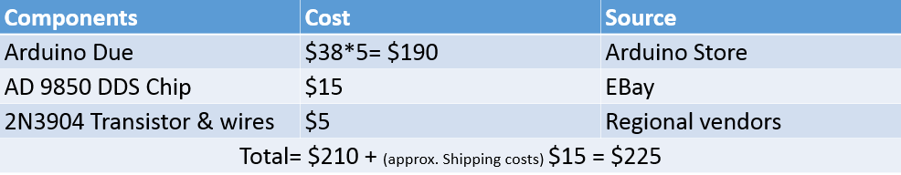
Pulse programmers are an important part of MRI systems with proprietary hardware and are cost prohibitive. Other implementations of pulse programming consoles reported, use Complex Programming Logic Device 1, DSP’s 2 and microcontrollers which have higher development costs and time, and are typically restricted to particular architectures. Hence, a console was developed using widely available Arduino Boards to interface with Pulseq-GPI 3, 4 implementations to provide an open source platform for integration with the MR research pipeline at a reduced cost of $225.Methods:
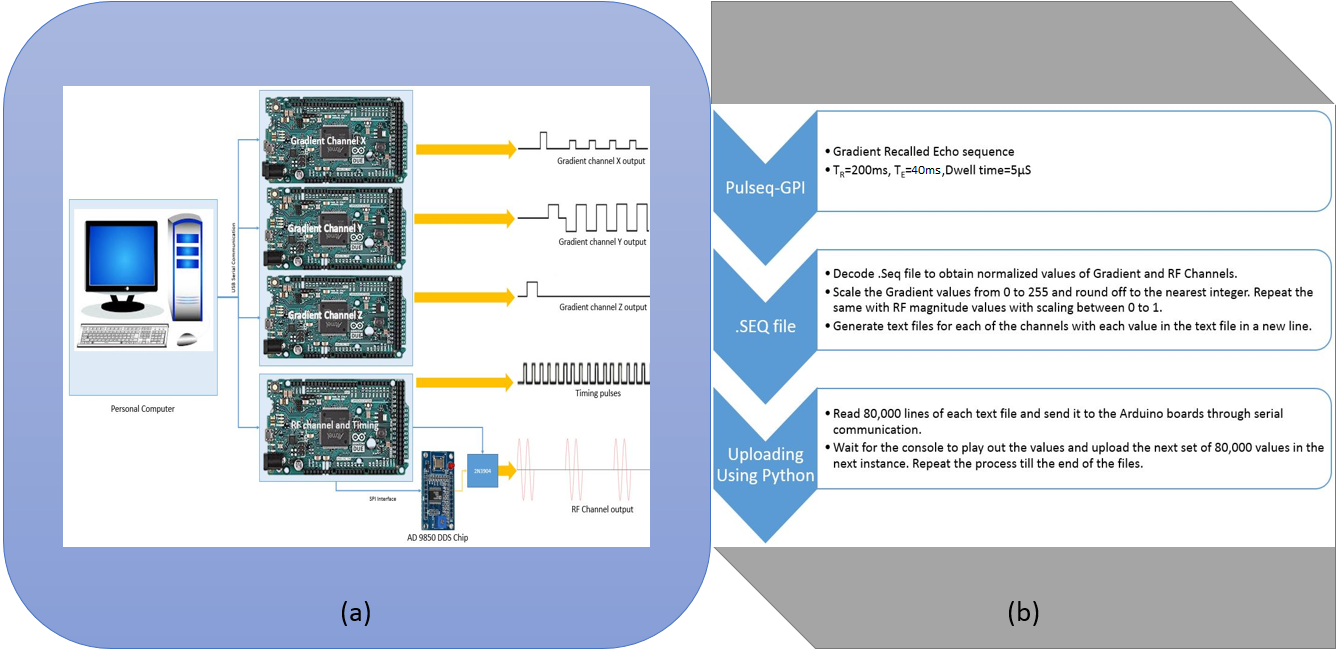
Hardware description: The console consists of three 32-bit general purpose Arduino DUE boards, one for generating timing and controlling Radio Frequency (RF) pulses, and one for each of the gradient channels (Gx, Gy), and can be easily extended to the third gradient channel (Gz), as shown in figure 1a. The RF-timer board was interfaced with AD9850 Direct Digital synthesizer chip configured to generate a 405 KHz RF sine wave, whose output was given to Collector of 2N3904 transistor. The output of the transistor was switched with pulses from the RF-timer to generate Rectangular RF pulses. The gradient boards (Gx, Gy) played out the gradient waveforms on their respective inbuilt Digital to Analog Converter (DAC) outputs. All the boards are interfaced with a personal computer (PC) through USB serial communication protocol to upload waveform data.
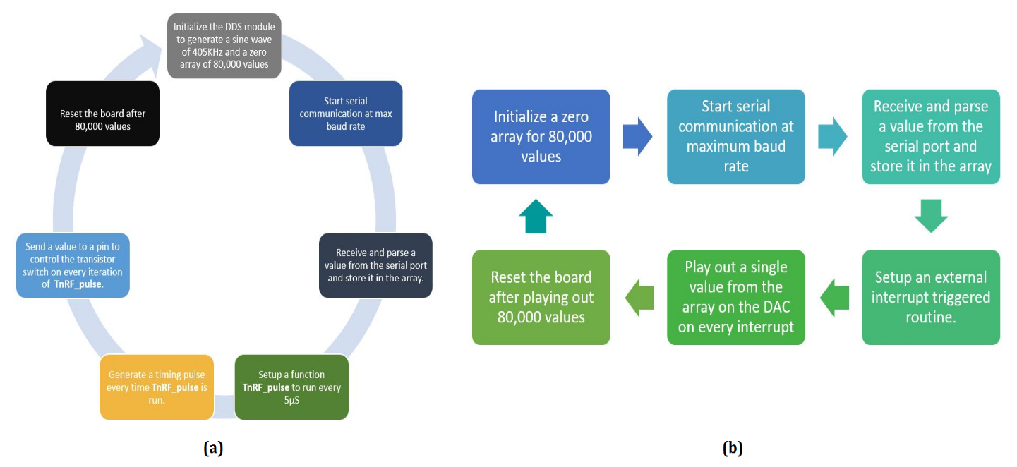
Software implementation: Pulseq-GPI based implementation generates a .seq file which has been decoded into three separate gradient files and one RF pulse file, and were uploaded to each of the respective boards with python running on PC, as shown in figure 1b. Data for two TR’s, which is 80,000 values were uploaded to the boards in one instance and played out, which took about 11.2 s. At every instance, the timer generated accurate synchronization pulses every 5 µs using timed interrupts of the DUE board. The gradient boards are interrupt driven and generated stored voltage values on their DAC’s with externally triggered interrupt from the RF-Timer board, which was also used to generate pulses to control the transistor switch depending on the stored RF magnitude values, as shown in figure 2. The system can be easily extended to add one more board for third gradient channel, which at present consists of three boards and could play out any two gradient channels along with RF channel. The cost of the console being developed is tabulated in figure 3.
Results:
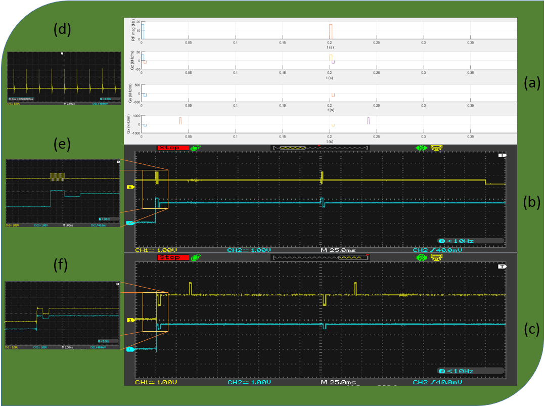
Arduino based hardware implementation reduces the complexity of the design and development processes in the MR pipeline. The designed hardware generated RF channel and Gradient channel waveforms in synchronous for a dwell time of 5 µs for 400ms (2 TR’s), as shown in figure 4b & 4c, which is analogous with figure 4a, the plot of uploaded data. An enlarged view of RF channel and Gz channel output is illustrated in figure 4e, similarly enlarged views of Gx and Gy values are displayed in figure 4f.Discussion and Conclusion:
This system demonstrated is a cost-effective solution to generate waveforms designed in Pulseq-GPI. The current work involves the integration of the system with ADC (for receive) and reducing the time required to upload the data for one instance (400ms) and/or interfacing the system with external memory cards to store larger sequence values. Future work involves interfacing the console with Coil driver apparatus to integrate with low field 9.5mT lab MRI systems.Acknowledgements
This research was supported by Ministry of Electronics and Information Technology, “National Mission on Indigenous MRI” 1(15)/2014-ME&HI, Department of Science and Technology (DST), grant No: DST/TSG/NTS/2013/100-G, No: DST/VGST/KFIST/LII/GRD333, and also under the program grant for “Development of a low field MRI scanner for stroke imaging”, No: INT/PORTUGAL/P-09/2017. The authors would like to thank Chennagiri Rajarao Padma for helping with the illustrations.References
- Stang, Pascal P., Steven M. Conolly, Juan M. Santos, John M. Pauly, and Greig C.Scott. "Medusa: a scalable MR console using USB." IEEE transactions on medical imaging 31, no. 2 (2012): 370-379.
- Hashimoto, Seitaro, Katsumi Kose, and TomoyukiHaishi."Development of a pulse programmer for magnetic resonance imaging using a personal computer and a high speed digital input–output board." Review of scientific instruments 83, no. 5 (2012): 053702.
- Layton, Kelvin J., Stefan Kroboth, FengJia, Sebastian Littin, Huijun Yu, Jochen Leupold, Jon-Fredrik Nielsen, Tony Stöcker, and Maxim Zaitsev. "Pulseq: A rapid and hardware-independent pulse sequence prototyping framework." Magnetic resonance in medicine (2016).
- Keerthi Sravan R, Imam Ahmed Shaik, Stefan Kroboth, Maxim Zaitsev, and Sairam Geethanath.” Implementation of Pulseq in GPI Lab” ISMRM 2017.
Figures