1724
A low cost Internet of Things solution for real time magnetic field measurement for MRI polarization coils using a computer numeric control machine1Medical Imaging Research Center, Dayananda Sagar Institutions, Bengaluru, India, 2Department of Radiology, Columbia University Medical Center, New York, NY, United States
Synopsis
An Internet of Things solution for real time Magnetic Field Measurement of polarization coils using Computer Numeric Control (CNC) machine was developed in order to automatically map the static magnetic field at a low cost ($722). The results were transformed into a visualization report of the magnetic field and uploaded on the cloud server. This report can be accessed by any authorized user with an internet connection from any device, to conduct further analysis. The magnetic field measuring CNC is a multipurpose 3-axis robotic system which can be equipped with other field probes to serve as a multi-parametric measurement device.
Purpose
Magnetic field strength measurement for MRI polarization coils manually using a Gauss meter is time consuming for a large set of observations, making it prone to human error. The use of a Computer Numeric Control (CNC) machine for high precision magnetic field measurements overcomes this challenge in a cost effective manner1. The current work aims at automatically measuring the magnetic field strength(B0) of the coils to a high accuracy at an even lower cost. To alleviate the challenges mentioned above, the Gauss probe was mounted to a 3-axis robotic CNC machine, for automation.Materials & Methods
The 3-axis robotic system used is an open sourced design by MIME Industries (mime.co.uk). The material of moving components is a non-magnetic acrylic plastic or also known as Poly Methyl Methacrylate (PMMA) with a thickness of 3mm. For the robotic arm movement, three power Pro 9 gram micro servos with a carry load of up to 0.75kg with an input requirement of 5V and 2A were used. The entire robotic arm was powered by either a phone charger or four AAA batteries connected in series as shown in Figure 2a. A 12 AWG copper coil of single layer, 9 turns with a coil diameter of 9cm was used as the MRI polarization coil. A point pattern with the coordinates for the 3-axis of the robotic arm as shown in Figure 1, was designed as per the dimensions of the copper coil. The robotic arm along with the Gauss probe was then programmed to move along the defined point pattern and measure the magnetic field strength of the coil. Each point was set manually by reading different voltages from three potentiometers through different analog pins of the Arduino UNO IDE 1.8.2, to obtain the angles for the corresponding points in the pattern .These values were converted by the Analog to Digital Converter (ADC), to digitised voltages between 0-1023, mapped to an angle between 0-180° and written to each servomotors as shown in Figure 2a. The analog B0 values sensed by the Gauss probe (on the robotic arm), were tapped from the Gauss meter at Vin and COM, and interfaced with the Arduino through the positive and the negative terminals of the Zener diode. The converted digital B0 values with the x, y and z axis coordinates of the point pattern, were simultaneously updated to an excel sheet using MATLAB (The Mathworks Inc., MA). The ThingSpeak IoT platform2 then ran the MATLAB code on the cloud which analysed the data on the excel sheet and produced the visualizations report. This generated a report which was available to be accessed from anywhere to conduct further analysis as shown in Figure 2b. The claw of the robotic arm was modified into a harness to ease the mobility of the probe at definite positions without much change in angle by the robotic arm.Results & Discussion
Figure 3 shows the table for the cost of equipment ($722) for the entire setup. To validate the accuracy and the repeatability of the magnetic field strength measurements by the CNC Machine, three experiments (with the coil carrying currents of 1,2 and 3A) were conducted to compare with the manual experiment measurements. Figure 4a, Figure 4b and Figure 4c shows the histogram for the B0 values obtained for these experiments. It was observed that there were slight variations in the B0 values obtained between the manual and automated CNC experiments. This is due to the resolution of the Gauss meter and the ADC which can be rectified. Figure 5a shows the UI depicting the visualization report of the magnetic field strength measurement for the coil when carrying 3A current. Figure 5b shows the screenshot of the visualization report on the ThingSpeak IoT Cloud Server for 3A current which was generated simultaneously.Conclusion
The accuracy and the repeatability of the measurements by the CNC machine has been verified as shown in Figures(4a-c).Therefore, an IoT solution for real time Magnetic Field Measurement using CNC can be employed to aid rapid building and characterization of MRI polarization coils. Magnetic Field measuring CNC is a programmable multipurpose 3-axis robotic system that can be employed in applications requiring reproducible millimetre measurements in particular.Cloud based analytics report which is generated allows the measurements to be accessed from anywhere at anytime. Future work involves making a mobile CNC machine to measure more resolute magnetic fields, larger coils and geospatial mapping of magnetic fields.Acknowledgements
No acknowledgement found.References
1. Winter L, Han H, Niendorf T, “COSI Measure – Open Source Multipurpose Measurment Systen”, Proc Intl Soc Magn Reson Med, 2016 #2200
2. Sharmad Pasha. “Thingspeak Based Sensing and Monitoring System for IoT with Matlab Analysis“. “. International Journal of New Technology and Research (IJNTR), Vol 2, Issue 6, 2016, pp 19-23.
Figures
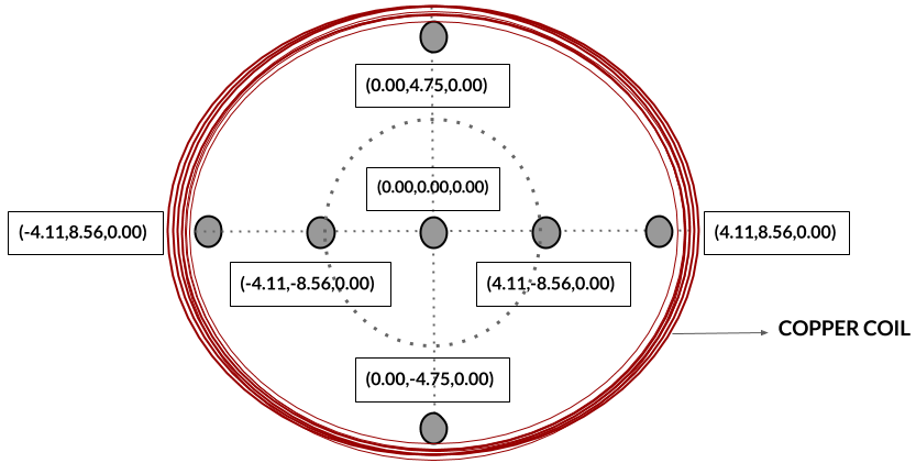
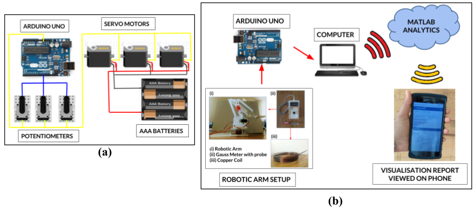
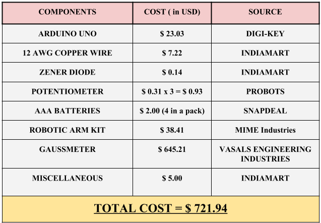
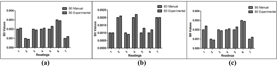
Figure 4 - (a)The histogram shows a comparison of the B0 values between the manual and automated experiments for a 1A current carrying coil. (b) The histogram shows a comparison of the B0 values between the manual and automated experiments for a 2A current carrying coil. (c)The histogram shows a comparison of the B0 values between the manual and automated experiments for a 3A current carrying coil.
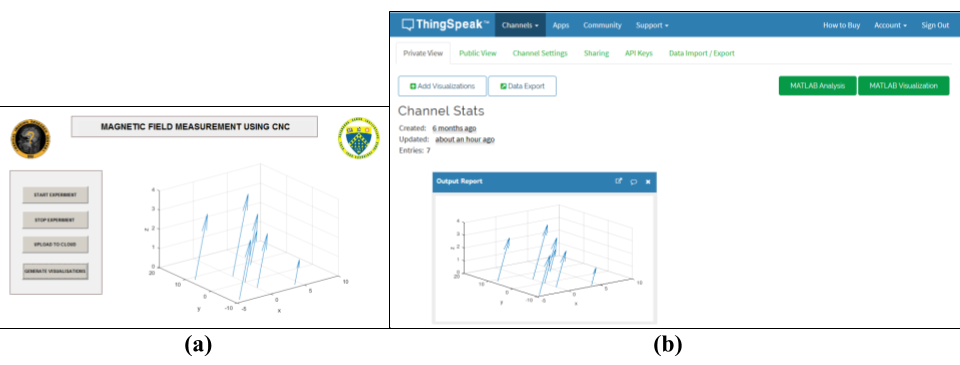
Figure 5 - (a) User Interface depicting the visualization graph for the B0 values for 3A current carrying coil.(b) Screenshot of the visualization graph generated simultaneously on the ThingSpeak IoT server for 3A current carrying coil.