1723
Tunable Phase Shifters and Ratio-adjustable Power Splitters for Array-compressed Parallel Transmission and MR Fingerprinting1Department of Biomedical Engineering, Vanderbilt University, Nashville, TN, United States, 2Vanderbilt University of Imaging Science, Vanderbilt University, Nashville, TN, United States, 3Department of Radiology, Vanderbilt University, Nashville, TN, United States, 4Department of Electrical Engineering, Vanderbilt University, Nashville, TN, United States
Synopsis
Array-compressed parallel transmission was recently proposed as a way to reduce the number of RF power amplifiers required for many-coil parallel transmission [1]. This is achieved by connecting a large number of coils to a small number of amplifiers via an array compression network that implements optimized coil-to-channel combinations using ratio-adjustable power splitter (RAPS) circuits [2,3] and phase shifters. Currently, the RAPS circuit ratios are determined by tuning coaxial cable lengths within the RAPS circuit (Figure 2), but this prevents dynamic switching of the compression weights via remote tuning. Remotely tunable RAPS circuits and phase shifters would also be useful for dynamic mode switching in MR fingerprinting [4,5]. To achieve this, here we describe the design and validation of a quad hybrid-based phase shifter that can be tuned by varying terminating capacitors, and integrate it into a RAPS circuit. Bench tests and 7T imaging and B1+ mapping experiments were performed to validate the phase shifters and new RAPS circuit design.
Introduction
Array-compressed parallel transmission was recently proposed as a way to reduce the number of RF power amplifiers required for many-coil parallel transmission [1]. This is achieved by connecting a large number of coils to a small number of amplifiers via an array compression network that implements optimized coil-to-channel combinations using ratio-adjustable power splitter (RAPS) circuits [2,3] and phase shifters. Currently, the RAPS circuit ratios are determined by tuning coaxial cable lengths within the RAPS circuit (Figure 2), but this prevents dynamic switching of the compression weights via remote tuning. Remotely tunable RAPS circuits and phase shifters would also be useful for dynamic mode switching in MR fingerprinting [4,5]. To achieve this, here we describe the design and validation of a quad hybrid-based phase shifter that can be tuned by varying terminating capacitors, and integrate it into a RAPS circuit.Methods
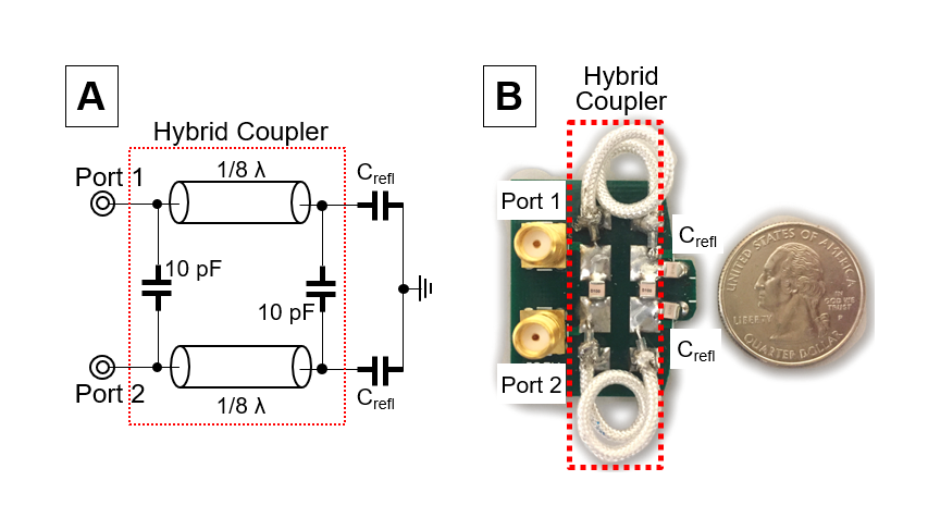
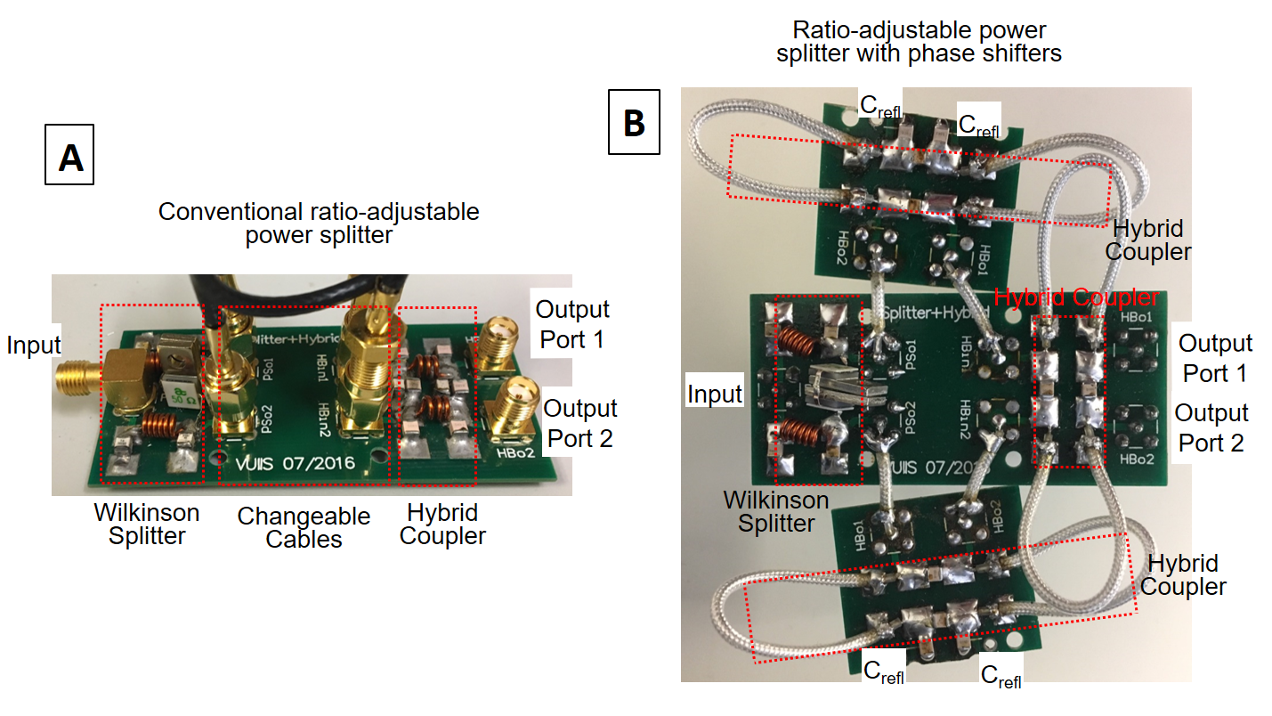
Circuits Figure 1a shows the proposed phase shifter circuit. The phase shift between ports X and Y is determined by the terminating capacitors, as: $$$\theta= \pi-2\tan^{-1}*\frac{Z_{L}}{Z_{0}}$$$ where $$${Z_{L}}=\frac{1}{2\pi*f*C}$$$ and $$${Z_{0}}=50$$$. The capacitances could be remotely varied using methods such as PIN diode-switched capacitor banks [6,7], varactors [8], and piezoelectric motors connected to variable capacitors [9]. Figure 1b shows a constructed circuit. Figure 2a shows our previous RAPS circuit design with fixed coax cables that set the output ratio, and Figure 2b shows a new RAPS circuit with phase shifters in place of the cables. The RAPS circuit output voltage ratio is a function of the phase shifts: $$$ratio = \mid{\cot\frac{\phi_{1}-\phi_{2}-\frac{\pi}{2}}{2}}\mid$$$ where $$$\phi=-\frac{3}{2}\pi+\theta$$$ . The RAPS circuit was tuned to 298MHz, each port was matched to have no greater reflection than -20dB, and the isolation between the output ports was no greater than -25dB for the across output voltage ratios.
Experiments B1+ maps were measured using a Philips Achieva 7T scanner (Philips Healthcare, Best, Netherlands) and one port of a birdcage coil (Nova Medical Systems, Wilmington, MA, USA). The RAPS circuit was inserted between the scanner and the 0-degree port of the birdcage coil, and the other ports of the RAPS circuits and the coil were terminated with 50 Ohm loads. B1+ maps were acquired using the DREAM method [10] across voltage ratios, and a reference map was collected with no RAPS circuit inserted. The overall power loss of the circuit was calculated from S-parameters measured on the bench and verified from the B1+ maps.
Results
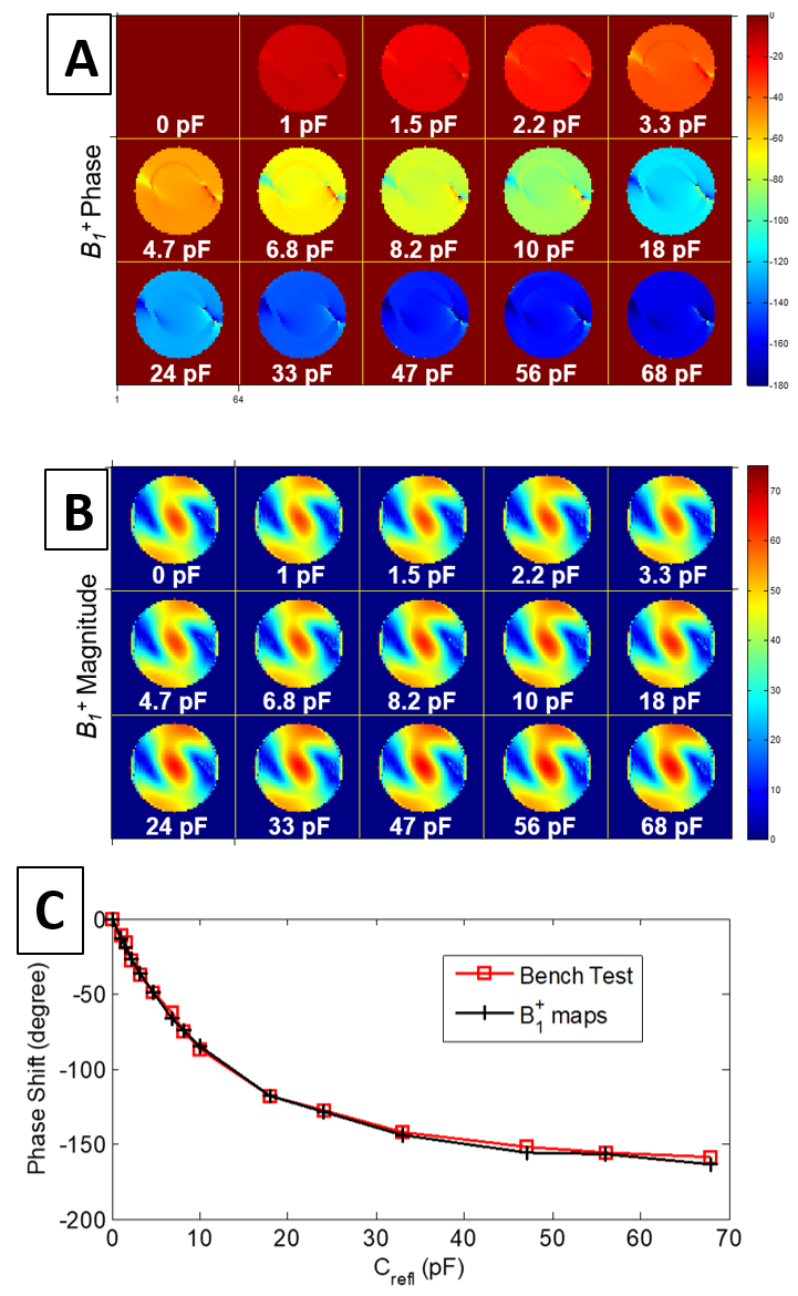
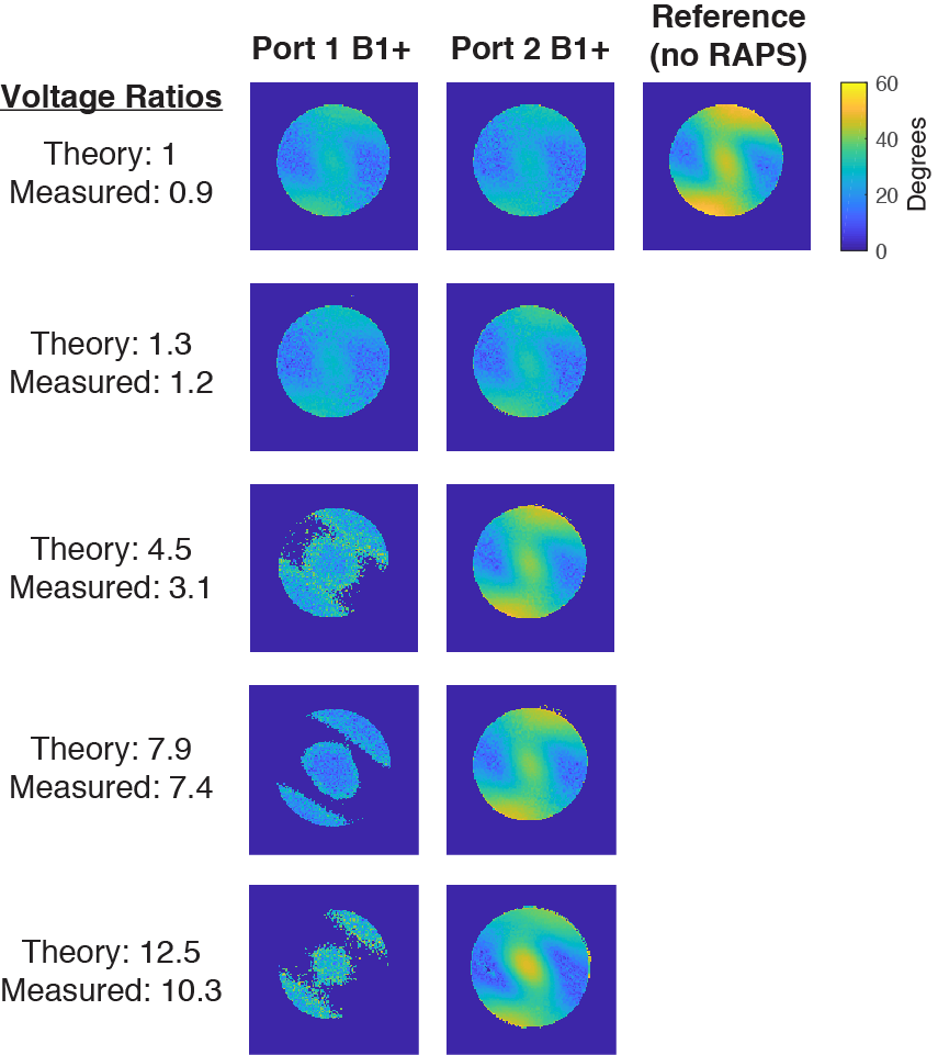
In figure 3c, it is shown that as the terminating capacitance on the hybrid coupler increases the phase shift decreases. A capacitance range of only 1-68pF gives phase shifts of up to 150 degrees. There is no appreciable change in B1+ magnitude between phase shifts. The measured bench tests were in good agreement with the B1+ maps (Figure 4). As the voltage ratio increases, the B1+ maps for port 2 approach the B1+ reference map in amplitude. In addition, as the ratio continues to increase the difference in signal between the two ports in the B1+ maps noticeably increases, as expected. With a voltage ratio of 1, ports 1 and 2 are predicted to be equal. From the bench tests, the ports are matched to within 0.5 dB of each other. This even split is seen in the B1+ maps. Overall power loss of the circuit was calculated to be between 22-25%.Discussion
The bench measurements and B1+ maps (Figure 4) validated that the quad-hybrid phase shifters allow us to adjust ratios without inserting unacceptable loss into the system. The work following these results will include remotely adjusting the capacitance from outside the scanner using PIN diode switched capacitor banks. Once the circuit is remotely tunable, it can be incorporated into a full remotely tunable acpTx network. In addition, the phase shifters and RAPS circuits could enable dynamic B1+ mode switching in MR fingerprinting.Conclusion
We have presented and validated a capacitance-based phase shifter design that facilitates remote tuning, and integrated it with a ratio-adjustable power splitter for array-compressed parallel transmission. These will enable the implementation of remotely tunable array-compression networks with low loss.Acknowledgements
Supported by NIH R01 EB 016695 and U01 025162References
1. Cao, Z., Yan, X., & Grissom, W. A. (2016). Array‐compressed parallel transmit pulse design. Magnetic resonance in medicine, 76(4), 1158-1169.
2. Yan, X., Cao, Z. and Grissom, W. A. (2017), Ratio-adjustable power splitters for array-compressed parallel transmission. Magn. Reson. Med.. doi:10.1002/mrm.26847.
3. Yan X, Cao Z, Grissom WA. Experimental implementation of array-compressed parallel transmission at 7 Tesla. Magn Reson Med 2016;75:2545–2552.
4. Cloos, M. A., Knoll, F., Zhao, T., Block, K. T., Bruno, M., Wiggins, G. C., & Sodickson, D. K. (2016). Multiparametric imaging with heterogeneous radiofrequency fields. Nature communications, 7.
5. Mehta B, et al. (2017), Improving uniqueness of MRF signal evolutions using an integrated parallel receive, excitation, and shimming (iPRES) coil array. ISMRM Workshop on Magnetic Resonance Fingerprinting.
6. Garver, R. V. (1972). Broad-band diode phase shifters. IEEE Transactions on Microwave Theory and Techniques, 20(5), 314-323.
7. White, J. F. (1974). Diode phase shifters for array antennas. IEEE transactions on Microwave theory and techniques, 22(6), 658-674.
8. Garver, R. V. (1969). 360/spl deg/Varactor Linear Phase Modulator. IEEE transactions on microwave theory and techniques, 17(3), 137-147.
9. Keith, G. A., Rodgers, C. T., Hess, A. T., Snyder, C. J., Vaughan, J. T., & Robson, M. D. (2015). Automated tuning of an eight‐channel cardiac transceive array at 7 tesla using piezoelectric actuators. Magnetic resonance in medicine, 73(6), 2390-2397.
10. Nehrke K, Bornert P. DREAM - A novel approach for robust, ultrafast, € multislice B1 mapping. Magn Reson Med 2012;68:1517–1526
Figures