1722
Endoluminal coil-sensitivity degradation with the coil-orientation effect with respect to B0 field: preliminary results1Univ. Lyon, INSA-Lyon, Université Claude Bernard Lyon 1, UJM-Saint Etienne, CNRS, Inserm, CREATIS UMR 5220, U1206, F-69000, LYON, France, 2General Electric Healthcare, Buc, France, 3General Electric Healthcare, Aurora, OH, United States
Synopsis
Single-loop endoluminal RF-coils are a possible solution for the SNR limitations of external coils. However, they suffer from signal variations due to the coil sensitivity dependence with the coil orientations with respect to the B0 field. We simulated (electromagnetic simulations with Feko) an RF-coil along the Ox axis (0°) taken to be that of the B0 field and for specific coil orientations (30, 45, 60 and 90°) around and in oblique position with respect to the Ox axis (B0). We then evaluated the signal distribution (H-field 2D map) variation with the coil orientations to can propose an adequate architecture.
Introduction
Magnetic Resonance Imaging
(MRI), based on an array of external receiver coils, is usually used for
medical diagnosis of abdominal and gut diseases to provide an improved Signal-to-Noise
Ratio (SNR). However, the latter is not sufficient to depict thin bowel and
colon wall1. For this purpose, previous works
have demonstrated the value of internal (endoluminal) coils close to the region
of interest2–4. However, single-loop endoluminal
RF-coils suffer from the signal variations due to the coil sensitivity
dependence with various possible coil orientations with respect to the magnetic
field B05. In fact, a single loop RF-coil has a
maximal sensitivity when its axis is aligned with the main magnetic field B0
(The RF B1 is orthogonal to the B0). This is considered
as the reference orientation. In all other orientations of the coil, the signal
distribution changes; thus the sensitivity and subsequent image quality
decrease. This is a major challenge in clinical colon diagnosis. One solution
is the development of endoluminal RF-coil based on the combination of different
loops to be able to cover different orientations. The purpose of this work was
to simulate, the effect of different orientations of the RF-coil with respect
to the B0-field on the signal distribution.Methods
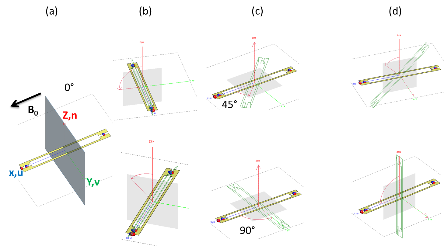
We simulated using a commercial electromagnetic software based on the moment method (Feko) a rectangular-loop (5.1x47 mm2) endoluminal receiver coil. The Ox axis was taken to be that of the B0 field and aligned along the length of the coil (fig. 1a). Other orientations were simulated by rotating the coil either about the Ox axis (45 and 90°) (fig. 1b), the Oy axis (fig. 1c) or the Oz axis (fig. 1d). Then the magnetic field (H-field) 2D-maps (slice perpendicular to the plane of the coil) were extracted considering only the components perpendicular to the direction of the B0 (i.e. Ox) that can probe the transverse magnetization.Results
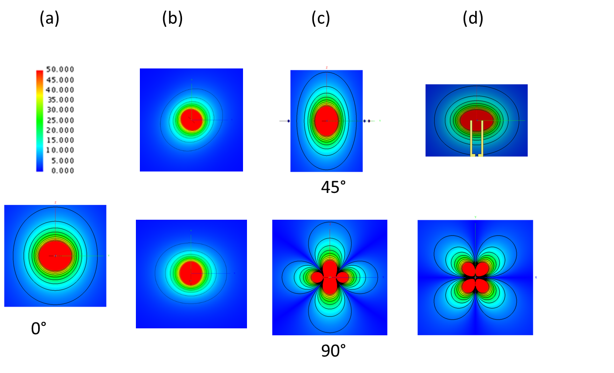
Simulations showed that rotating the coil around the Ox axis do not change significantly signal distribution (fig. 2b) compared to the reference orientation (0°) (fig. 2a). This was different when the coil is rotating around the Oy or Oz axis where large variations of the signal distribution were observed. For a 90° angle around the Oy or Oz axis, signal distribution is a four-leaf clover shape with cancelation along diagonals (fig. 2c,d).Discussion/Conclusion
These preliminary results show the dependence of the signal distribution of the coil as a function of the orientation of the coil with the B0 field. Large variations occur when the coil is perpendicular to the main magnetic field B0 (four-leaf clover shape). These variations degrade the coil sensitivity. Reconfigurable-loops geometries could provide a solution to minimize the loss of signal and maximize the homogeneity. Further work will work with architecture which is able to operate in several orientations and we will investigate reconfigurable coil made of different elements by using Micro Electro-Mechanical System (MEMS) switches, developed by GE Healthcare, to activate some loops and deactivate others to operate in any orientations with optimal sensitivity.Acknowledgements
Authors would like to thank the LABEX PRIMES of University of Lyon, which has supported this work within the program "Investissements d'Avenir" (ANR-11-IDEX-0007) operated by the French National Research Agency (ANR).References
1. Beuf O, Pilleul F, Armenean, M., Hadour, G. & Saint-Jalmes, H. In vivo colon wall imaging using endoluminal coils: Feasibility study on rabbits. J. Magn. Reson. Imaging. 2004;20:90–96.
2. Hurst, G. C., Hua, J., Duerk, J. L. & Cohen, A. M. Intravascular (catheter) NMR receiver probe: Preliminary design analysis and application to canine iliofemoral imaging. Magn. Reson. Med. 1992;24:343–357.
3. Gilderdale, D. J. et al. Design and use of internal receiver coils for magnetic resonance imaging. Br. J. Radiol. 1999;72:1141–1151.
4. Dorez H et al. Endoluminal high-resolution MR imaging protocol for colon walls analysis in a mouse model of colitis. Magn. Reson. Mater. Phys. Biol. Med. 2016;29:657–669.
5. Atalar, E. et al. High resolution intravascular MRI and MRS by using a catheter receiver coil. Magn. Reson. Med. 1996;36:596–605.
Figures