1721
Remote tuning and matching of a non-resonant wire loop1Department of Radiology and Imaging Sciences, University of Utah, Salt Lake City, UT, United States
Synopsis
There are several situations, such as some interventional applications or intracavitary placement, where it would be desirable to remotely tune and match a local RF coil. Although remote lumped element placement will result in decreased SNR, it is likely that net loss in SNR may be a function of the designs used. This study investigated the SNR trade-off of different methods of remote tuning by comparing the SNR that could be achieved with the placement of lumped elements at the coil. A large variation in SNR based on method was observed.
Motivation
There are several applications where a local RF coil is desirable, but a standard RF coil with lumped element components is precluded for space or environmental constraints. For these situations, an RF coil with remote lumped element components might be used. These applications might include receiver coils placed in the path of a therapeutic ultrasound beam or inserted into a living organism. For these applications, it is likely that the SNR that can be achieved will depend on the manner in which remote tuning and matching is applied.
This study investigated the performance of different methods of remote tuning and matching. The design constraints for this work were that the coil be a single conductive loop without lumped element components, that the cable length between the loop and the tune/match circuit be arbitrary, and that the loop operates in a receive only configuration, requiring it to be decoupled during the transmit portion of the pulse sequence. Other authors have presented solutions to the remote tuning problem, but most are based on half-wave cables and other use a partial match at the coil and a fine-tuned remote match [1-4]. Here we investigate the SNR tradeoffs for different types of remote tuning and matching schemes where the lumped elements are completely remote. These schemes were investigated for a range of cable lengths.
Methods
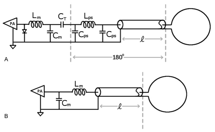
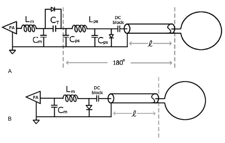
For this work, five different loops were constructed using different tuning and matching networks and different cable lengths. The different tuning and matching schemes were compared using measured SNR results from each loop. All imaging experiments were done on a Siemens PRISMA scanner (Siemens Medical Solutions). Each of five different loops was made from 16 AWG copper wire and were approximately 6.8 cm in diameter. The loops were connected to the matching network using non-magnetic RG-316 coax cable (Thermal Wire and Cable, LCC). As a reference standard of the SNR that could be achieved without the remote lumped element constraint, one of the loops was tuned and matched using a standard shunt capacitor and series inductor match circuit at the loop with a short 3cm cable connecting it to the preamplifier. The other 4 loops used remote tuning and matching techniques with a coax cable connecting the loop to the tune and match circuit. Two loops were constructed with 20cm cables and two loops were constructed with 40cm cables. One loop for each cable length was connected to the match circuit through a 180° phase shifter which included the cable and a lumped element π-phase shifter to provide the phase shift that the cable didn’t provide (see Figure 1A). The other two match circuits were simply matched to the cable input impedance as shown in Figure 1B. In the construction process, it was found that the active decoupling for the phase-shifted loops was not as strong as expected. It was found that placing a short circuit across the end of the cable provided a better decoupling of the loop. This technique was implemented in all the remote tuning circuits as shown in figure 2. SNR images were acquired using a standard GRE sequence (TR/TE=100/4ms, flip angle of 25°, 20cm FOV, 128x128).Results
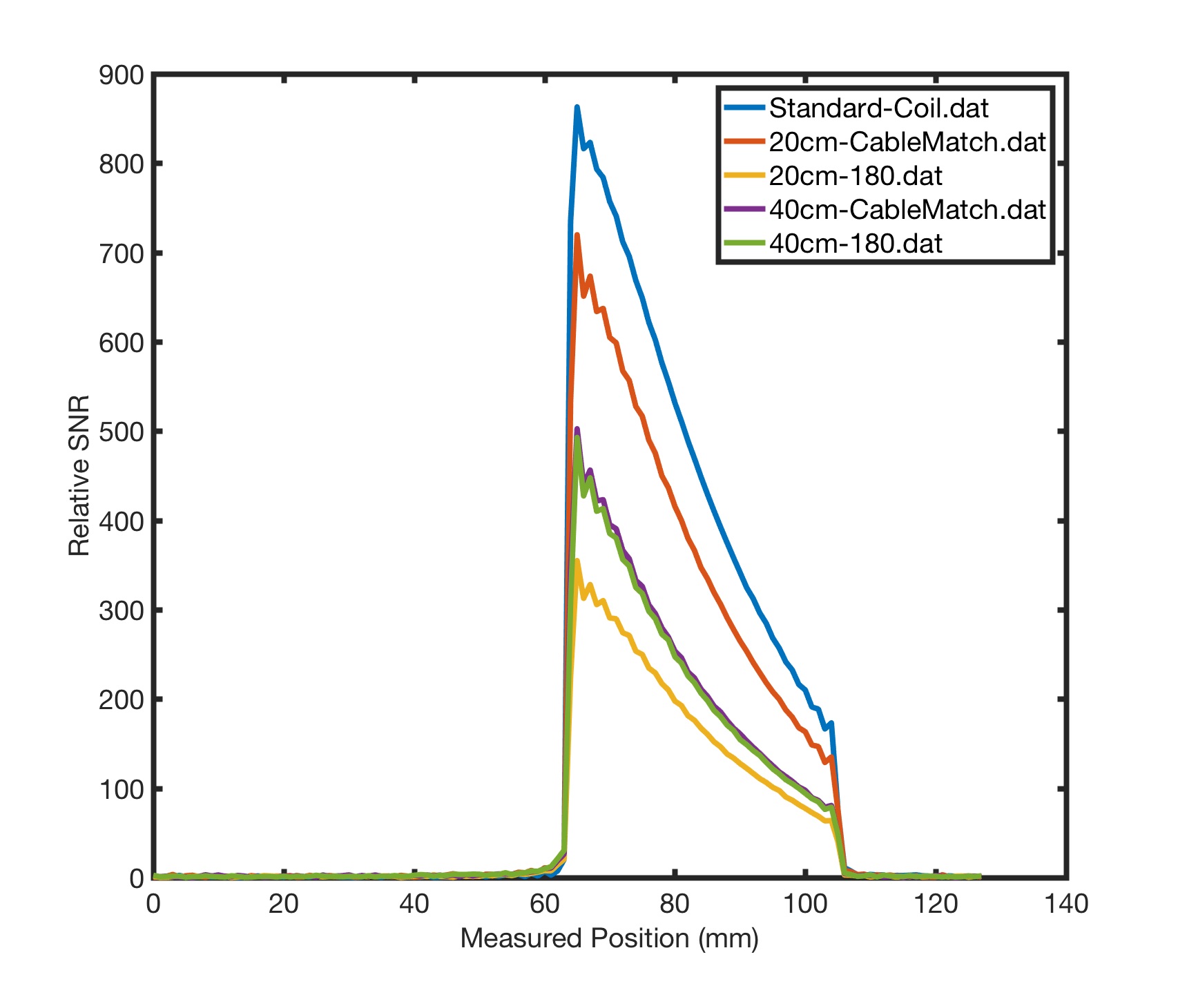
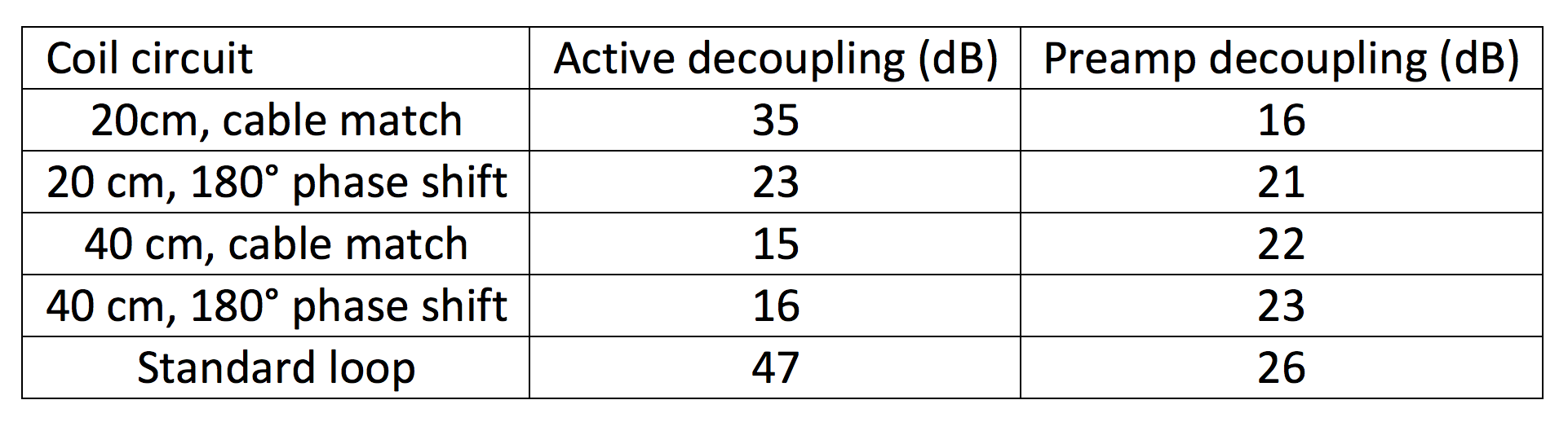
The active decoupling results are given in Table 1 and the SNR results are given in Figure 3. For this study, the 20cm cable with the cable match had the best SNR performance of the remote tune and match configurations. Both the 180° phase shifted circuits were outperformed by the cable match counterparts, indicating that the extra circuitry required to achieve the 180° phase shift may not be as ideal as a standard low loss cable with the same phase shift. Although not shown, we observed that for active decoupling, the diode placed across the match circuit has a narrow resonance while the diode across the cable has a very broad resonance, killing nearly all possible coupling.Discussion and Conclusion
This study observed a wide variation in SNR performance for different methods of remote tuning, indicating that improved SNR might be obtained by attention to other details not studied here. Given the constraints of this study, it was expected that the resulting SNR would be reduced from a standard loop design. However, even for cases where it is not possible to place lumped element components on the conductive loop, these techniques allow the construction of a loop coil that can provide significant increases in SNR compared to having no loop at all. Although preamp decoupling was not a significant part of this study, the preamp decoupling was achieved with these designs.Acknowledgements
Supported by NCI R03CA195453-02. Special thanks to Lorne Hofstetter and Emilee Minalga.References
1. Matsuoka Y et al. High-Resolution MR Imaging of Gastrointestinal Tissue by Intracavitary RF Coil with Remote Tuning and Matching Technique for Integrated MR-endoscope System. Conf Proc IEEE Eng Med Biol Soc. 2013;2013:5706-10.
2. Alastair JM et al. An Expandable Intravenous RF Coil for Arterial Wall Imaging. J Magn Reson Imaging 1998 Jan-Feb;8(1):226-34.
3. Quick HH et al. Single-Loop Coil concepts for Intravascular Magnetic Resonance Imaging. Magn Reson Med. 1999 Apr:41(4):751-8.
4. Rath AR. Efficient Remote Transmission Line Probe Tuning. Magn Reson Med. 1990 Mar:13(3):370-7.
Figures