1719
Optimization study of a double-tuned nested birdcage RF coil for 1H/23Na MRI1Life, Health and Environmental Science, L'Aquila University, L'Aquila, Italy, 2Laboratori Nazionali del Gran Sasso, Istituto Nazionale di Fisica Nucleare, L'Aquila, Italy, 3Istituto SPIN-CNR, CNR, L'Aquila, Italy
Synopsis
The nested birdcage design is useful to develop dual tuned volume transceiver RF coils. Despite its apparently simple design, coupling among coils affects the resonance frequencies, making its practical realization cumbersome. FEM simulations were first validated by workbench measurements for a specific nested double-birdcage suitable for 1H/23Na MRI at 2.35T. Then were used to study the isolation and RF efficiency for a set of different geometrical parameters. We demonstrate that an optimized nested design is obtained if the disposition of the birdcages rugs, lengths and shield diameter are carefully taken into account.
INTRODUCTION
Several specific configurations of double-tuned MRI RF coils have been described1-4 for the acquisition of co-registered X-nuclei and proton images with good B1 homogeneity and large FOV. Among them an appealing configuration is based on the coaxial assembly of two birdcages, each one tuned at the frequency of the desired nucleus5-6. Despite its conceptual simplicity, the resonant frequency shifts induced by the mutual coupling make its tuning cumbersome or requires extra lossy elements (i.e. traps on each rung). In this work, we focus on the optimization of a dual-tuned 1H/23Na based on the nested birdcage RF transceiver configuration, suitable for a pre-clinical 2.35T scanner. We have studied the RF coils’ isolation and efficiency for a set of useful geometries. To this purpose FEM numerical simulations have been first validated against the workbench measurements of a 2.35T prototype and then used to explore the performances for different geometrical configurations.METHODS
We first build and performed FEM simulations (Ansys HFSS v.17.2, Eigenmode analysis) of coaxially arranged double-birdcage (Fig. 1) with an inner 23Na Low Pass (LP, 26.5MHz), an external 1H High Pass (HP, 100.3MHz), and an outer RF shield (S). The FEM simulations and workbench measurements were used to determine the % shift of the resonant frequencies (Df%) of the useful 1H mode of the unshielded (LP+HP) and shielded (LP+HP+S) configurations compared to the isolated HP birdcages (HP; HP+S) for a range of azimuthal angles. The simulations and measurements agreement is very good, within few % (Fig. 2). FEM simulations were extended for several values of the birdcages length ratios, shield diameters and azimuthal angles estimating the Df% of the 1H and 23Na useful modes (Fig. 3). The same simulations were used to study the effect of coils mutual coupling on the electric and magnetic field maps, by means of normalized field profiles (Fig. 4). The Ansys Eigenmode modality is able to calculate the correct field profiles, not their absolute field intensities. To assess the issue of RF coil efficiency at both resonant frequencies, a 50 Ohm port with appropriate matching capacitor was inserted in the FEM design. Using the Driven Modal approach and a matching condition better than -25dB, the B1 field for unit RF input power at 1H and 23Na frequencies (Fig. 5) could be accurately evaluated.RESULTS
The effect of mutual coupling affects strongly the high frequency mode, and is practically not relevant for the low frequency one. The azimuthal angle has an effect on mutual coupling with a minimum condition for 22.5deg, corresponding to the rungs of the inner coil midway between the rungs of the outer coil. This simulation confirms previous experimental evidence5-6. Surprisingly the presence of the shield strongly reduces the coupling, as it gets closer to the outer birdcage. The coupling is reduced if the LP is shortened (note the scale of the upper and lower panel in Fig. 3) thus suggesting another possible design strategy. The B1 profiles are relatively insensitive to the presence of the second coil (Fig. 4) while the B1 intensities have consistent reduction especially for the 1H mode and the longer LP (Fig. 5).DISCUSSION
The level of mutual coupling in the nested double-tuned birdcage design can be greatly reduced if the optimal azimuthal angle is chosen, the RF shield is located close to the external birdcage and the LP is as short as possible. RF coil efficiency of the 1H mode is affected by the geometry of the LP coil, but this is often not an issue in preclinical applications.CONCLUSION
Our extensive FEM simulation study, confirmed by workbench measurement with a 2.35T prototype, shows the optimization strategies to be followed for the design of nested double-tuned birdcages RF coils. Our FEM results can be easily extended to large size nested RF coils for UHF MRI clinical applications.Acknowledgements
No acknowledgement found.References
1. M. Alecci, et al. Practical design of a 4 Tesla double-tuned RF surface coil for interleaved 1H and 23Na MRI of rat brain. J. Magn. Reson. 181:203-211 (2006).2. F. Wetterling, et al. A double-tuned 1H/23Na dual resonator system for tissue sodium concentration measurements in the rat brain via Na-MRI. Phys. Med. Biol. 55, 7681–7695 (2010).
3. G.C. Wiggins, et al. High-performance radiofrequency coils for 23Na MRI: brain and musculoskeletal applications. NMR Biomed. 29:96-106 (2016).
4. N.K. Bangerter, et al. Sodium MRI radiofrequency coils for body imaging. NMR Biomed. 29:107-118 (2016).
5. A. Asfour, A three-coil RF probe-head at 2.35 T: potential applications to the 23Na and to the hyperpolarized 129Xe MRI in small animals. International Conference IEEE-EMBS, pp. 5693–5699 (2010).
6. R.C Brand et al. Design and Performance of a Transformer-Coupled Double Resonant Quadrature Birdcage Coil for Localized Proton and Phosphorus Spectroscopy in the Human Calf Muscle at 7 T, CMRA 42:155-164 (2013).
Figures
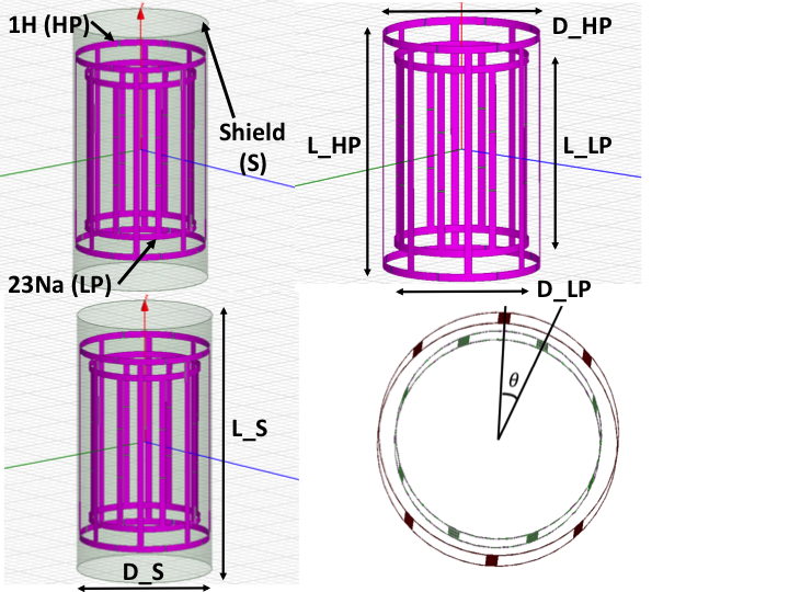
The coaxial double-tuned nested birdcage design with an 8 rugs 1H High Pass (HP), an 8 rugs 23Na Low Pass (LP) and the RF shield (S). The structure is characterized by a range of RF coil and shield diameter (D_HP, D_LP, D_S), length (L_HP, L_LP, L_S), strip width (W_HP, W_LP), tuning capacitor (TC_HP, TC_LP) and azimuthal angle (THETA).
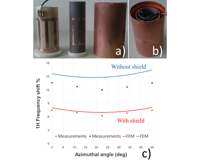
a) The 8 rugs HP (left), LP (center) and shield (right) with: D_HP=100mm, L_HP=160mm, W_HP=13mm, TC_HP=47pF; D_LP=75mm, L_HP=130mm, W_LP=6mm, TC_LP=470pF; D_S=140mm, L_S=240mm. b) The assembled nested double-birdcage RF coil ready for VNA measurements. c) % shift of the 1H resonant frequency due to HP-LP coupling from workbench measurements (points) and FEM simulations (lines) in the unshielded (blue) and shielded (red) configurations.
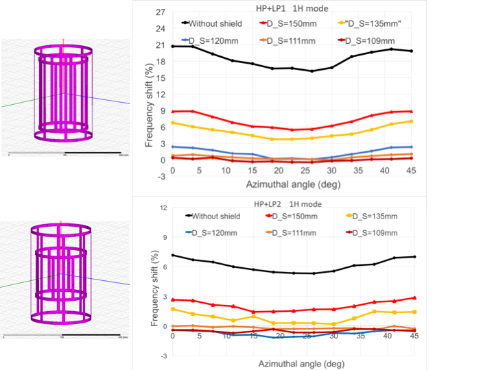
The simulated RF coil includes an 8 rugs HP (D_HP=105mm, L_HP=160mm, W_HP=5mm) with: (top) an 8 rugs “long” Low Pass (LP1; D_LP1=75mm, L_HP1=130mm, W_LP1=5mm); (bottom) an 8 rugs “short” Low Pass (LP2; D_LP2=75mm, L_HP2=80mm, W_LP2=5mm). Simulations were performed without or with shield having L_S=210mm and different diameters: D_S=150, 135, 120, 111, 109mm. The Df% of the useful 1H mode is obtained at several azimuthal angles for both the “long” (LP1, top) and short (LP2, bottom) Low Pass. The Df% of the 23Na useful mode is not shown, since it is within +/-2% for all the geometrical conditions considered.
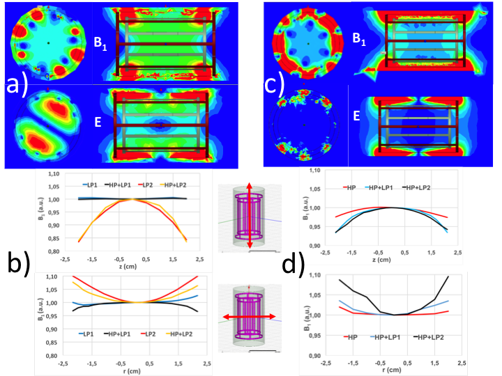
Figure 4
B1 and E field maps (a) and B1 profiles (b) for the 23Na useful MRI mode at 2.35T. Corresponding B1 and E field maps (c) and B1 profiles (d) for the 1H useful MRI mode. Geometrical size as in top of Fig. 3, D_S=120mm, the azimuthal angle among resonators 22.5deg and the Ansys Eigenmode simulation modality was used. (b) and (d): the B1 field profiles are for HP+LP1 (“long” LP) and HP+LP2 (“short” LP) configurations along the longitudinal Z axis and the central diameter of the birdcages. B1 profiles are normalized at the center.
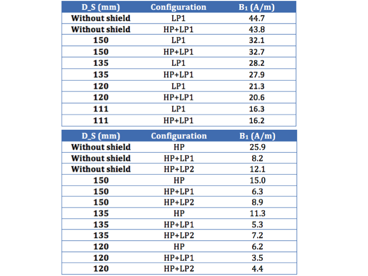
B1 field amplitudes (A/m) at the coil center obtained from the Ansys Driven Modal simulations (1W of power on the port, matching condition better than -25dB), geometry as in Fig. 3 and azimuthal angle equal to 22.5deg. With one port on the “long” Low Pass (LP1) and no port on the HP we measure the effect of the HP presence on the 23Na mode field amplitude (upper panel). The same with one port on the HP and no port on the “long” (LP1) or “short” (LP2) Low Pass for the field amplitude of the 1H mode (lower panel).