1718
Decoupling strategies for Double Tuned Radio Frequency coils at 7T1Pisa Division, National Institute of Nuclear Physics, Pisa, Italy, 2GE Healthcare, San Diego, CA, United States, 3IRCCS Stella Maris, Imago7 Foundation, Calambrone,Pisa, Italy, 4University of Cambridge, Cambridge, United Kingdom, 5GE Healthcare, Aurora, OH, United States
Synopsis
Magnetic Resonance Imaging (MRI) and Spectroscopy (MRS) with nuclei different from protons, often require the acquisition of proton signal for shimming and co-registration procedures. For this purpose Double Tuned Radio Frequency (DT-RF) coils are needed. The drawback of DT-RF coils is basically the coupling between the two resonant structures, which reduces SNR and increases focal heating. The aim of this study is to compare active and passive decoupling strategies in terms of Q factor and S21 parameter. Workbench measurements show that PIN Diode active decoupling is an interesting alternative for DT-RF coils.
Introduction
Magnetic Resonance Imaging (MRI) and Spectroscopy (MRS) with nuclei different from protons (X-nuclei), often require the acquisition of proton signal for shimming and co-registration procedures. Double Tuned Radio Frequency (DT-RF) coils allow to improve these procedures, avoiding the movement and the repositioning of the patient during the examination. The drawback of DT-RF coils is the coupling between the two resonant structures, which reduces SNR and increases focal heating. The aim of this study is to compare active and passive decoupling strategies.Methods
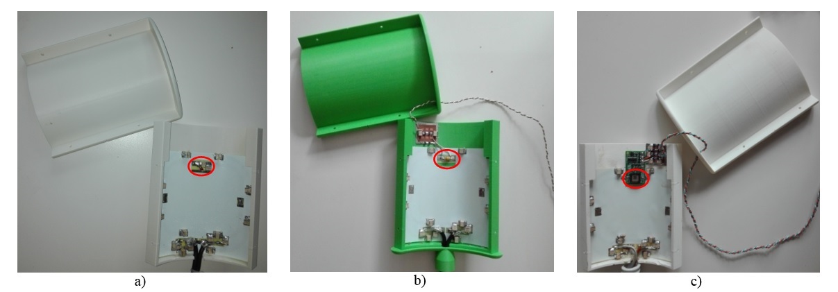
In order to compare decoupling circuits performances, three identical DT-RF coils were built (Fig.1). The three prototypes consist of two concentric loops, where outer and inner loops are tuned at proton (298.03MHz at 7T) and sodium (78.86 MHz at 7T) Larmor frequencies, respectively1. In the first prototype passive decoupling is obtained through the insertion of a trap circuit2. In the other two prototypes decoupling is obtained through the insertion of two active elements: a PIN Diode and a Micro-electromechanical System (MEMS)3,4.
In the three prototypes the decoupling elements act as a switch, which opens the inner loop, tuned at sodium Larmor frequency, when proton signal is transmitted/received (see Fig.2). The hypothesis that underlies this choice is that: the amount of current than flows in the proton loop at sodium frequency is negligible, because the equivalent reactance exhibited by proton tuning capacitances is high at sodium frequency. The trap circuit is a shunt LC circuit that acts as a high impedance at its resonance. In our case the trap circuit is tuned at proton frequency and is inserted in the inner loop, which is tuned at sodium frequency. The opposite is not feasible, as inserting the trap circuit, tuned at sodium frequency, in the outer loop prevents the re-tuning of the outer loop at proton frequency, because the trap-equivalent reactance is too high. Thus, the previous hypothesis is mandatory in case of passive decoupling, but it is optional for active decoupling. The active element was not inserted into the outer loop to more accurately compare the performance of three coils when differing only in the decoupling circuit.
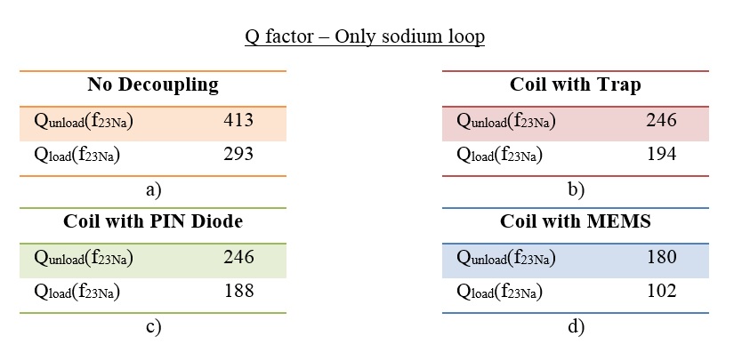
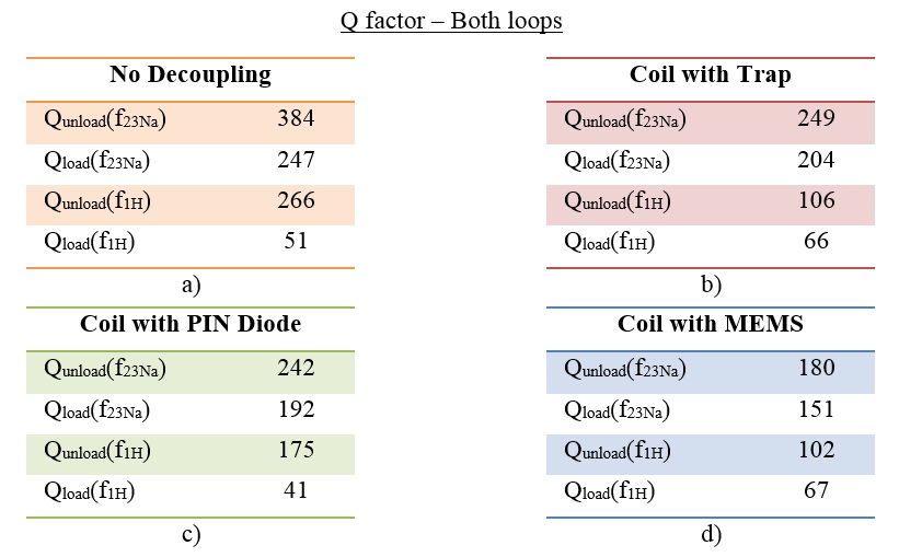
To go beyond the passive decoupling limitation an active decoupling method is proposed. DT-RF coils performances with two active elements, PIN Diode and MEMS switches, are compared in terms of coil Q factor and S21 parameter. In order to evaluate the Q factor degradation due to the decoupling element, the inner loop is tuned at sodium frequency leaving the outer loop open and the Q factor of the inner loop is compared with the Q factor of the same loop with the decoupling element inserted. Obtained results are showed in Tab. 1. Furthermore to compare the final performances, both loops of the three prototypes are tuned at their own Larmor frequency and the Q factor is compared at both resonant frequencies (see Tab. 2).
Results
The Q factor of the coil with PIN Diode is comparable with the Q factor of the coil with trap (> 240), while the Q factor of the coil with MEMS is less than the other two. The lower Q factor of the coil with trap at proton frequency with respect to the case of the sodium loop alone (194 vs 106) is probably due to the coupling between the trap circuit and the proton loop, tuned at the same frequency.
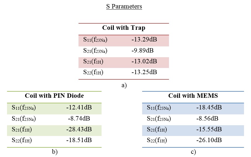
The decoupling capability was quantified through the S21 parameter.
The S21 of the coil with trap is comparable with the S21
of the other two coils at sodium frequency (S21(f23Na)<-8dB), but the
S21 of the coil with PIN Diode at proton frequency is the best (<-28dB).
Discussion and Conclusions
Since the Q factor of the coil with PIN Diode is comparable with the Q factor of the coil with trap, the degradation obtained with PIN Diode active decoupling is comparable to the degradation obtained with the standard passive decoupling. The S21 parameter of the coil with PIN Diode at proton frequency is the best. The S21 of the three coils at sodium frequency is comparable because at sodium frequency both loops are closed. Indeed we supposed that amount of current than flows in the proton loop at sodium frequency is negligible and as a consequence the coupling at sodium frequency is negligible. But in case of active decoupling there is the possibility of inserting the switch in the outer loop too, further increasing the decoupling at sodium frequency. Thus, active decoupling with PIN Diode can be an interesting alterative decoupling strategy for DT-RF coils.Acknowledgements
Royal Society Exchange Schema, IE150411References
1. Kaggie et al, “7 T Sodium/Proton Knee Imaging: First Results”, UHF ISMRM Symposium, 2016;
2. M. Alecci et al, “Practical design od 4 Tesla double-tuned RF surface coil for interleaved 1H and 23Na MRI of rat brain, JMR 181 (2006) 203–211;
3. D. Spence, M. Aimi, “Custom MEMS Switch for MR Surface Coil decoupling”, Proc Intl Soc Mag Reson Med. 2015
4. S. B. Bulumulla et al, “MEMS switches integrated RF coils and array for magnetic resonance Imaging”, ISMRM conference, 2015
Figures