1715
High precision MR-TEM cell for in-situ calibration of RF field probes in clinical MR systems1Physikalisch-Technische Bundesanstalt (PTB), Braunschweig und Berlin, Germany
Synopsis
An MR-TEM cell is a transverse electromagnetic (TEM) cell operated as a Tx/Rx coil directly inside an MR scanner. From a precise flip angle measurement in a tiny sphere of water the RF electric field inside the cell can be determined using the TEM condition |E|=2c0|B1+|. Thus, an MR-TEM cell can be utilized for the calibration of RF E- and H-field probes as well as for the determination of the RF voltages and RF currents at its ports which is important e.g. for experimental validation of simulation results in RF safety research. We report here on the high precision flip angle calibration of an MR-TEM cell with 0.1% uncertainty.
Introduction
An MR-TEM cell is a transverse electromagnetic (TEM) cell operated as a Tx/Rx coil directly inside an MR scanner [1]. From a precise flip angle measurement in a tiny sphere of water the RF electric field inside the cell can be determined using the TEM condition |E|=2c0|B1+|. Thus, an MR-TEM cell can be utilized for the calibration of RF E- and H-field probes as well as for the determination of the RF voltages and RF currents at its ports [2,3] which is important for RF safety research. We report here on the high precision flip angle calibration of an MR-TEM cell with 0.1% uncertainty. To this end simple FID measurements covering the flip angle range of up to 400 degrees were performed avoiding any substantial relaxation time influence. Allowing for an inhomogeneous line broadening within the water sphere the spin dynamics during RF excitation was simulated using measured RF excitation pulse shapes. Furthermore, the influence of the input impedance of the preamplifier was explored showing the potential influence of radiation damping effects when using a narrowband GaAs-FET preamp.Methods
MR-TEM cell: A TEM cell with a septum distance of 3cm was constructed from printed circuit board material and a solid frame of polyethylene (PE). It was mounted on a solid PMMA support with a slider for reliable sensor positioning. A hollow PE sphere filled with pure water (i.d.=7mm) was placed inside a Styrofoam block in the center of the lower compartment (see Fig. 1).
FID measurements: All measurements were performed in a 3T MR scanner (Siemens Verio) using solely the transmit system of the scanner. Single FIDs were excited by 3-ms rectangular pulses with nominal transmitter voltages changed from 5V to 185V in steps of 5V. Both the low-level and the transmitted (amplified) RF pulses were coherently recorded with a two-channel high-speed digitizer card (Spectrum M3i.4142). The receive path consisted of either an active PIN-diode T/R-switch together with a low impedance narrowband GaAs-FET preamplifier or a passive T/R-switch together with a 50-ohm broadband preamplifier (F=1.5dB). To avoid any T1 influence the interval between the experiments was > 20s. After down-conversion and decimation the initial complex valued amplitude of the FID signal was determined by fitting a mono-exponential decay with a residual frequency offset which was typically less than 3Hz. Nevertheless, T2* was in the order of 40ms indicating substantial inhomogeneous line broadening.
Model: The complex valued FID signal amplitude after spin excitation was assumed to be SFID=kAMP·Mx(t0) whereas the flip angle α is assumed to be $$\alpha\cdot k_{FA}=360°\cdot\int_{0}^{t_{0}} S_{Tx}(\tau)d\tau$$ with STx(t) being the real part of the measured RF pulse shape. The inhomogeneous line broadening was modelled by 3 discrete spin populations: One on-resonant population and two off-resonant populations at frequencies of ±BW. The density ratio Δ of the on-resonant and the off-resonant population together with the other parameters kAMP, kFA, and BW were fitted to the measured FID signal amplitudes using full Bloch simulations of the spin excitation process.
Results and Discussion
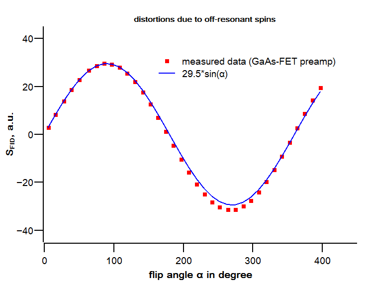
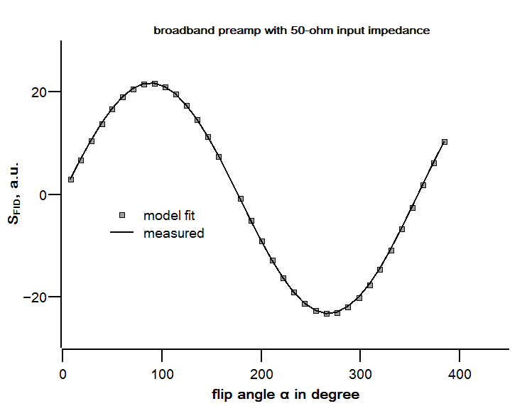
In Fig.2 it is shown that the measured FID amplitudes differ considerably from a sinusoidal Rabi oscillation. This is attributed to off-resonant spins due to inhomogeneous line broadening. When using the simple assumption of 3 discrete spin populations excellent agreement between measured data and modelled data can be achieved for booth kinds of preamplifiers (see Fig.3 and Fig.4). However, the fit-residuals show that utilizing a narrowband GaAs-FET preamplifier causes small but clearly detectable systematic model deviations of the order of 10-4 (see Fig.5). We attribute this to effects of radiation damping. On the other hand, when using a broadband preamplifier with an input impedance of 50 ohm nearly perfect model fitting can be achieved with no systematics in the residuals. From these data it can be estimated that kFA and hence the flip angle itself can be determined with an uncertainty of 0.1%, provided the system is stable over the measurement period.Conclusions
We have shown that flip angle measurements using an MR-TEM cell can be performed with 0.1% uncertainty. To achieve this accuracy inhomogeneous line broadening must be included into the signal modelling. The usage of a broadband 50-ohm preamplifier avoids model inconsistencies which are probably due to effects of radiation damping. The increased accuracy of the flip angle calibration can be transferred to an increased accuracy of in-situ fiber-optic RF field probe calibrations, which are needed, e.g., for MR-safety assessments of metallic implants.Acknowledgements
We thank M. Steinhoff for assistance during the measurements.References
[1] Klepsch T, et al., Calibration of fiber-optic RF E/H-field probes using a magnetic resonance (MR) compatible TEM cell and dedicated MR measurement techniques, Biomed. Tech. 57, Suppl. 1 (2012) 119 - 122, doi:10.1515/bmt-2012-4428.
[2] Weidemann G, et al., A system for calibrated measurements of RF electro-magnetic fields inside a clinical MR scanner, Proc. Intl. Soc. Mag. Reson. 22 (2014) 1370.
[3] Weidemann G, et al., RF current measurements in implanted wires in phantoms by fiber optic current clamps, Proc. Intl. Soc. Mag. Reson. Med. 23 (2015) 1852.
Figures

Left: MR-TEM cell made of printed circuit board material in a robust polyethylene frame. A fiber-optic RF E-field probe is positioned in the upper compartment while the lower compartment contains a water-filled hollow polyethylene sphere inside a Styrofoam block.
Right: Example: RF E-field measurements using a body phantom. The MR-TEM cell on the patient bed of the MR scanner is used for in-situ calibration of the fiber-optic E-field probe.