1714
A Dual-Tuned 70 cm Whole-Body Resonator for 13C and Proton MRI/MRS at 3TEd Boskamp1, Zhentian Xie2, Victor Taracila1, Amy Stephen2, Mike Edwards2, Tim Skloss2, Ralph Hurd3, Fraser Robb1, and Joe Murphy-Boesch4
1G. E. Healthcare Technologies, Aurora, OH, United States, 2G. E. Healthcare Technologies, Waukesha, WI, United States, 3Radiological sciences lab, Stanford University, Palo Alto, CA, United States, 4NINDS-NIH, Bethesda, MD, United States
Synopsis
Hyperpolarized 13C enhances the SNR of signals from 13C metabolites. Separate transmit and receive coils are inserted into the magnet bore to image 13C, limiting patient space. Here, a dual tuned 13C /1H body coil is developed that is capable of imaging both proton and 13C in one exam. The coil has the same 70 cm inner diameter as the standard body coil and can be used stand-alone as the Tx/Rx coil, or as the transmit coil for proton and 13C receive arrays. The efficiency for proton excitation is comparable to that of the standard proton only body coil.
Introduction
Hyperpolarization of 13C is known to enhance the SNR of the 13C resonance by orders of magnitude1 and has been used to image prostate cancer in humans at 3T.2 For prostate imaging, a 13C transmit coil is positioned around the patient separate from the 13C endorectal receive coil, limiting space for the patient.2 Here, a dual tuned whole body coil based on the four-ring birdcage3 is described that is capable of imaging both 1H and 13C simultaneously. The coil has the same 70 cm diameter and proton field of view as the standard body coil. It can be used in Tx/Rx mode, or it can be de-tuned for use with receive-only arrays for either nucleus.Methods
Using ½ inch copper tape conductors, 8 inch diameter, 8¼ inch long scale models were built of (1) a regular high-pass 16-rung proton birdcage, (2) overlapped 16 rung birdcages (proton, HP and 13C, LP)4 with ½ inch gap between end-rings, and (3) a dual tuned 4 ring birdcage type ( ½ inch between end-rings) first reported by Murphy-Boesch et al.3 All coils were surrounded by a 9¼ inch diameter RF shield. Based on the results of scale model testing, the four-ring birdcage was chosen and developed as a full scale 70 cm whole body coil (Fig 1). The low-pass 13C mode is developed by the inner 16-rungs birdcage; the high-pass proton mode by the outer birdcages coupled through the inner birdcage. The rung capacitance was 40 pF and the outer end-ring capacitance was 33 pF per segment. 1 nF capacitance was inserted on the inner rings to prevent gradient eddy currents. 127 MHz baluns were applied to the carbon-mode and proton-mode drive cables to prevent E-field induced shield currents. Both modes were matched to a 75kg patient and driven in quadrature. FEM analysis using HFSS (Ansys,Inc) was used to calculate the fields and RF current density patterns. The body coil was mounted in a standard 3T 70 cm MRI system with multi-nuclear capability (Discovery MR750W, GE Healthcare, Waukesha, WI). The net forward power to the coil was measured with directional couplers during a calibrated pulse sequence with known B1+ magnitude derived from a 10 cm spherical Si oil phantom for proton and an 18 cm spherical ethylene glycol phantom for 13C. The field of view in the z-direction was measured using pick up loops. Lab tests on volunteers using two non-resonant pick up loops showed the relationship between patient size / shape and the Q of the coil in both modes.Results
At 127 MHz, scale models showed that coil losses for the four-ring birdcage were 0.7 dB worse than for the standard birdcage, but 0.9 dB better than the overlapped birdcages. The carbon efficiency (32 MHz) in the four-ring birdcage was also better than the overlapped birdcages by 4.5 dB. For the body coil, the low-pass modes of the inner birdcage and the high-pass modes of the coupled outer birdcages were well separated. FEM analysis (Figs 2 and 3) of the body coil at 127.7 MHz indicated that 31% of the current in the outer rings is returned by their neighboring inner rings, so ring currents, normalized to the outer rings, distribute as 1.0/-0.31/0.31/-1.0. The -6dB Z-FOV measured in the system was 52 cm for proton and 37 cm for 13C. The unloaded B1+ efficiency measured in the system was: 0.238 mT/sqrt(P) for 127 MHz and 0.271 mT/sqrt(P) for 32 MHz, where power P is in Watts. The unloaded Q’s were 280 for the proton mode and 180 for the carbon mode. The Q ratios measured in the lab using people of different weights were: Qempty/Q75kg = 2.8 for 127 MHz and Qempty/Q75kg =1.1 for 32 MHz. Phantom images showed both good uniformity and good SNR at 32 MHz (Fig. 4). Mode isolation was <-32dB at both frequencies with bandstop filters.Discussion
A 70 cm dual tuned birdcage with close coupled RF shield was developed. The gap between end-rings is narrower than in previous work3 (16% versus 25% of coil length) providing greater FOV for the carbon mode. The efficiency for proton excitation is comparable to that of a regular proton body coil, and the transmit efficiency for carbon is adequate to produce a 24 mT B1 field at the coil center with 8 kW of RF power. Addition of bandstop filters will allow simultaneous excitation at both frequencies.Conclusion
A dual tuned body coil can replace custom-built transmit coils for imaging hyperpolarized 13C without sacrificing performance of a standard body coil.Acknowledgements
No acknowledgement found.References
1. Ardenkjaer-Larsen, JH, Fridlund, B, Gram, A, et al. Increase in signal-to-noise ration >10,000 times in liquid-state NMR. PNAS 2003;100:10158. 2. Nelson, SJ, Kurhanewicz, J, Vigneron, D, et al. Metabolic Imaging of Patients with Prostate Cancer Using Hyperpolarized [1-13C]Pyruvate. Sci Transl Med 2013;5(198):1. 3. Murphy-Boesch, J, Srinivasan, R. et al. Two Configurations of the Four-Ring Birdcage Coil for 'H Imaging and 'H-decoupled 31P Spectroscopy of the Human Head. JMR 1994;B103:103. 4. Fitzsimmons, JR, Beck, BL, and Brooker, HR. Double Resonant Quadrature Birdcage. Mag Reson Med 1993;30(1):107.Figures
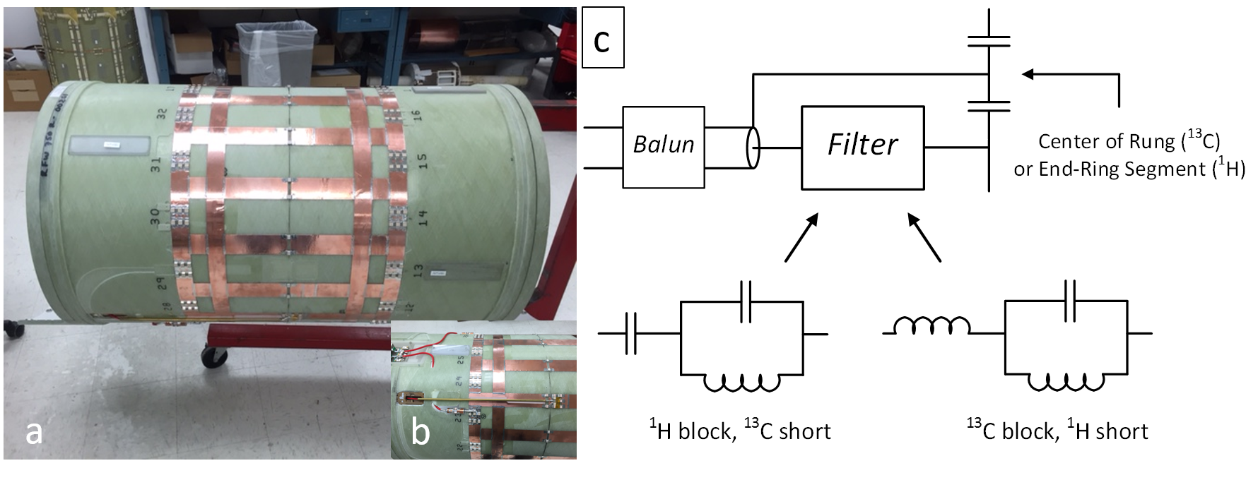
Fig 1A: Full scale model
of dual tuned coil with dimensions: coil radius 353mm, RF shield radius 373mm,
outer-ring and inner-ring widths 45 mm, gap between outer-rings and inner-rings
45mm, rung width 51mm, and total coil length 595 mm. B: drive scheme picture
before addition of filters, C: with filters, measured isolation is <-32 dB
at both frequencies.
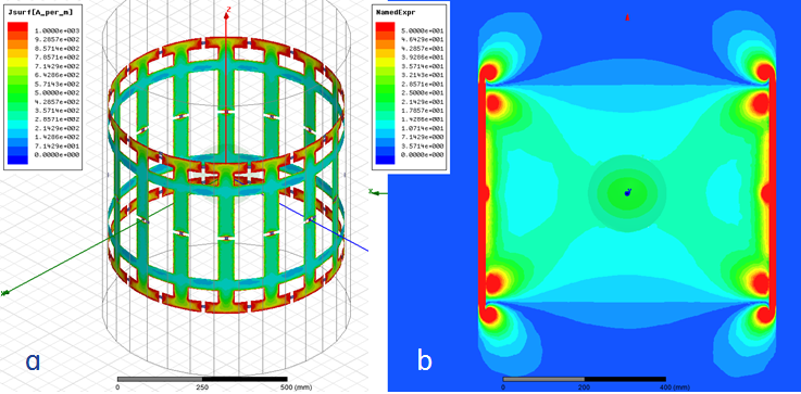
Fig 2 (a) Simulated RF current density and (b) B1+ field contours for the proton mode at
127 MHz. The coil contains a 20cm load sphere at isocenter, permittivity 60, conductivity 0.5 S/m
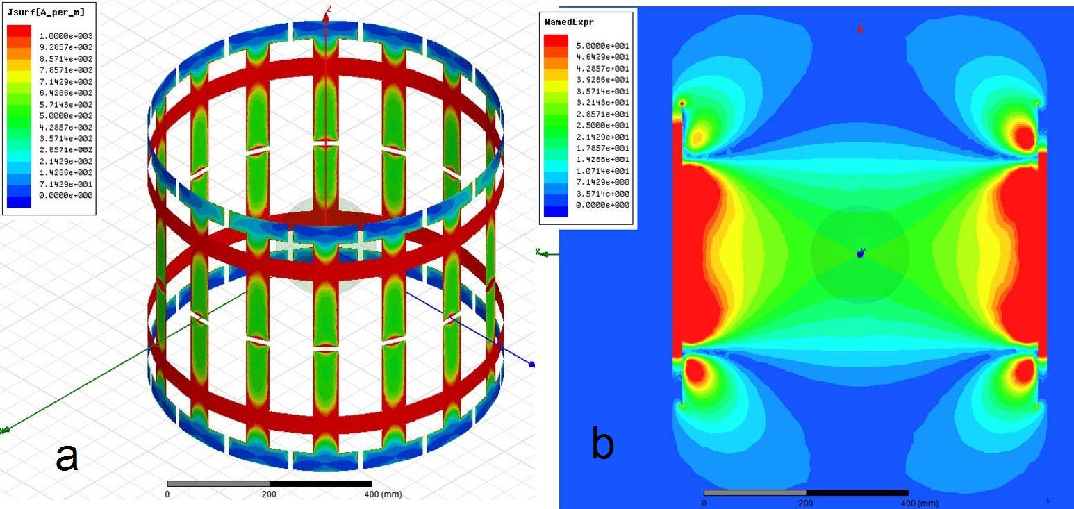
Fig 3: (a) Simulated RF current density and (b) B1+ field contours for the carbon mode at
32 MHz. The coil contains a 20cm load sphere at isocenter, permittivity 60, conductivity 0.5 S/m
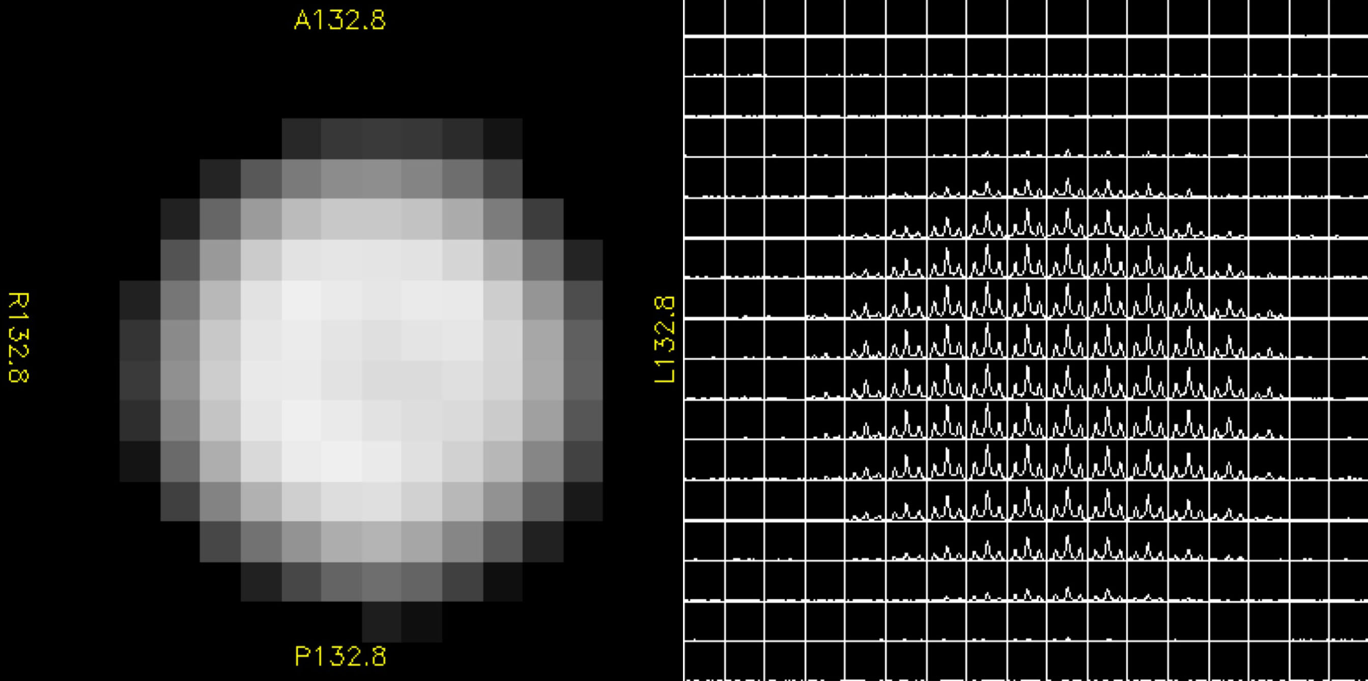
Fig 4:Carbon-13 body coil transmit-receive
images of an ethylene glycol sphere (18 cm diameter). Left: center peak
intensity image, with SNR 55:1. Right: CSI grid image, acquired with TR 75, 4
cm slice, FOV 50 cm, 16 x 16 CSI array, NEX 16, and 15-deg flip achieved in 500
μs with 820W transmit power.