1712
Using Noise Waves for Simulation and Measurement of Array SNR Penalty due to Passive Impedance Match1Invivo Corporation, Gainesville, FL, United States, 2Philips Research, Hamburg, Germany
Synopsis
Active impedance matching versus passive impedance matching of array coils is a concept well understood when designing transmit arrays. Lesser known however is that this concept also applies to receive arrays. Even though it appears that preamplifiers are noise matched to the passive port impedance (usually 50 Ohms), preamplifier noise coupling creates active noise match impedances which are mode dependent. In this context, a mode is defined by a signal vector and the corresponding weighting factors for optimum combined SNR. We use coupled noise waves to explain by simple concepts how the weighted and combined coupled noise changes the active noise match impedance.
Introduction
Receive array noise matching is a well-studied field [1-13], but the implications for MRI array coil design are often overlooked. We present a novel approach using noise waves and scattering parameters to explain matching to active array impedances. Active noise matching takes into account preamplifier noise via a modified noise covariance matrix. In case of using equal preamplifiers at all channels in a reciprocal antenna, the resulting noise match impedances are the equivalent of active array impedances for TX arrays. This complete noise model can also be used to demonstrate that preamplifier decoupling is mainly a convenience for tuning arrays, but has no impact on maximizing array SNR [6,7,10]. In cases of high Q coils and strong mutual coupling, coil designers can achieve significant SNR gains by matching to the active impedance of the dominant coil mode (typically the bird cage mode of volume arrays) to improve SNR. Our formulation provides solutions for active impedance match with LNAs having different input impedances Zin, and different noise figures Fmin, and we assume that optimum noise match impedance Zopt can be adjusted individually.
Methods
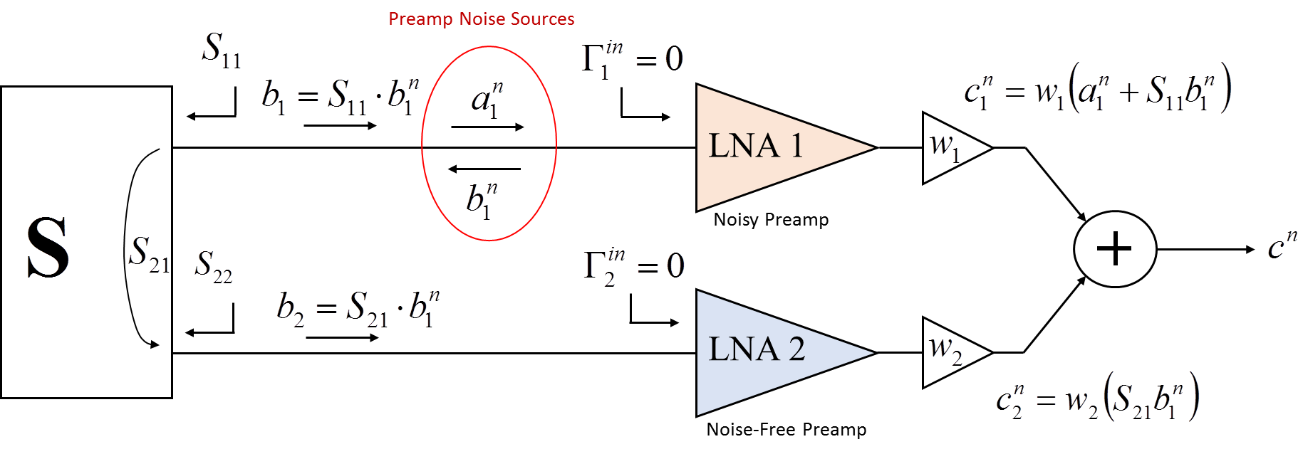
We are using a preamplifier noise model involving noise waves to simulate the noise coupling in the receive array [3, 13, 14, 15, 16]. This model places two noise waves at the input of a noise free amplifier. One wave travels toward the LNA, while the other travels into the coil array, represented by a scattering matrix S. The noise waves are uncorrelated when normalized to the optimum noise match impedance. It is also possible to normalize the noise waves to any other impedance, in our case the LNA input impedance. This formulation results in correlated noise waves, but has the advantage of avoiding reflection at the LNA inputs, therefore leading to a more compact formulation for the problem.
Figure 1 introduces the concept of active noise match for the example of two LNAs connected to an array. For the sake of the argument, we focus only on the noise emanating from LNA 1 and normalized the LNA gains to unity by including them in the weighting factors wi.
The weighted and combined noise from LNA 1 can be written as
$$\frac{1}{w_{1} } c^{n} =a_{1}^{n} +\underbrace{\left(S_{11} +\frac{w_{2} }{w_{1} } S_{21} \right)}_{\Gamma _{act} } b_{1}^{n} $$
Where w1 and w2 are the weighting factors used for the signal combination. It can be easily shown that noise contribution from LNA 1 is minimized for
$$\Gamma _{act} =\Gamma _{opt} =S_{11} +\frac{w_{2} }{w_{1} } S_{21}$$
This means, that optimum noise match for LNA 1 is achieved if the active reflection coefficient is equal to the optimum reflection coefficient. This is in contrast to traditional noise matching to passive reflection coefficient S11.
Extending this concept to large arrays, the active reflection coefficients become:
$$\Gamma _{opt}^{i} =\frac{1}{w_{i} } \sum _{k=1}^{N}w_{k} \cdot S_{ki} =\frac{1}{w_{i} } S_{i} w^{T} $$
Optimum weighting factors for a given signal vector Vcoil can be found by using the formula given by [17, 18]
$$w_{opt} =\left(\left[R_{coil} +R_{LNA}^{min} \right]^{-1} \cdot V_{coil} \right)^{*} $$
Rcoil and RLNAmin are noise covariance matrices for coil array and LNAs.
$$R_{LNA}^{min} =4kBR_{in} \left(T_{min} -S\cdot T_{min} \cdot S^{H} \right)$$
Tmin is a diagonal matrix containing the LNA minimum noise temperatures; Rin is the LNA input resistance. Optimum noise match coefficients are
$$\Gamma _{opt} =diag\left(w_{opt} \right)^{-1} S\cdot w_{opt} $$
Noise figure for a set of signals Vcoil can be calculated as
$$F_{dB} \left(V_{coil} \right)=10\cdot \log _{10} \left(\frac{V_{coil}^{H} \left(R_{coil} \right)^{-1} V_{coil} }{V_{coil}^{H} \left(R_{coil} +R_{LNA} \right)^{-1} V_{coil} } \right)$$
RLNA is the complete LNA noise covariance matrix
Results
For initial simulation we used a two channel array with both elements tuned to 50 Ohms, quality factor Q=50, resistive coupling kr=20%, magnetic coupling km=2%, minimum LNA noise figure NF_min=0.4dB and impedance matrix:
$$Z_{coil} =\left[\begin{array}{cc} {50\Omega } & {\left(10+j50\right)\Omega } \\ {\left(10+j50\right)\Omega } & {50\Omega } \end{array}\right] $$
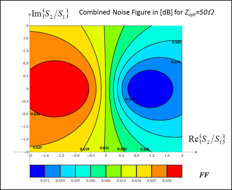
Maps were created showing combined array noise figure for different signal ratios S2/S1 and different matching conditions.
Fig. 2 shows a noise figure map for traditional passive match to 50Ω. The average NF for passive noise match was 0.8dB and minimum NF = 0.6dB.
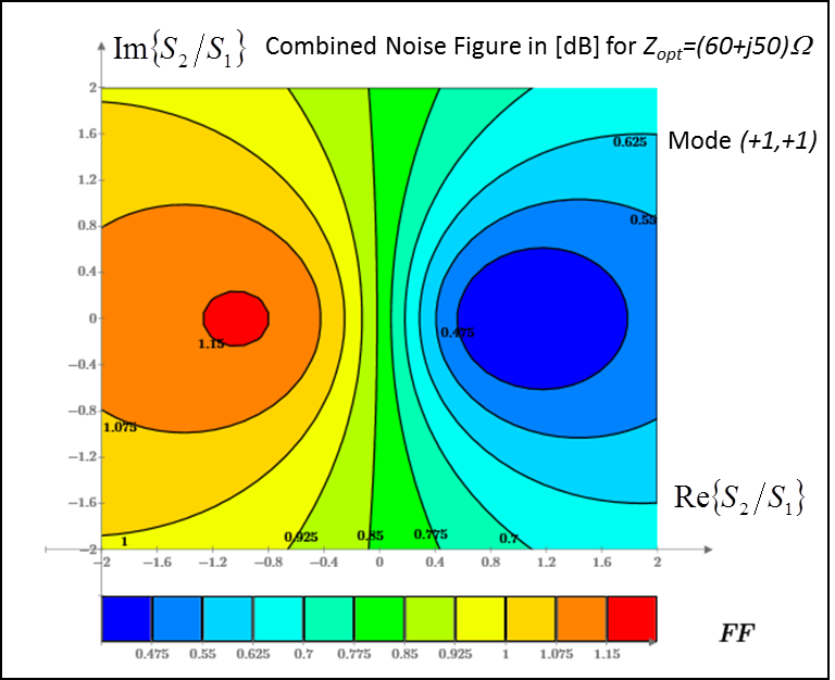
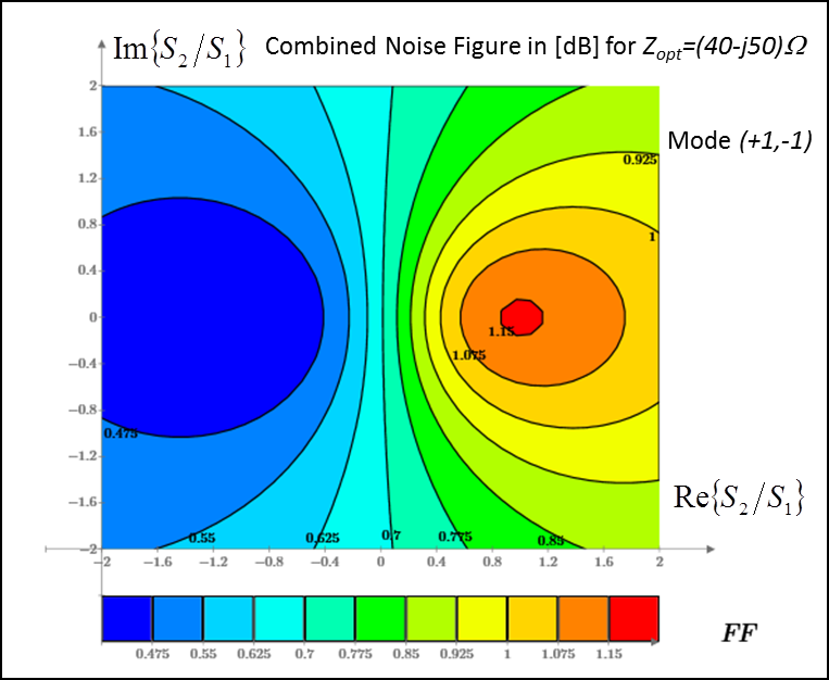
Fig 3 and 4 show active match to the signal mode (+1,+1) with Zopt=60Ω+j50Ω and signal mode (+1,-1) with Zopt=40Ω-j50Ω. For these two cases the average NF was 0.84dB and minimum NF = 0.4dB, the actual minimum NF for the preamps.
Conclusions
Coil coupling can have severe consequences for combined array SNR. If decoupling is not an option, active matching to the dominant mode can improve SNR. The preamplifier input impedance has no effect on combined SNR when all active channels and proper noise statistics are applied.Acknowledgements
In memoriam Dr. Charles Saylor, PhD. A great scientist and good friend. Gone too soon.References
- Reykowski A and Wang J, Rigid signal-to-noise analysis of coupled MRI coils connected to noisy preamplifiers and the effect of coil decoupling on combined SNR, Proc 8th ISMRM, Denver, Colorado, USA, April 2000, p. 1402.
- Maaskant R, Woestenburg E, Arts M, A generalized method of modeling the sensitivity of array antennas at system level, Proc 34th EuMC, Amsterdam,Netherlands, October 2004, pp. 1541–1544.
- Maaskant R, Woestenburg EM, Applying the Active Antenna Impedance to Achieve Noise Match in Receiving Array Antennas, Antennas and Propagation Society International Symposium, IEEE, Honolulu, HI,USA, July 2007, pp. 5889–5892.
- Warnick KF and Jensen MA, Optimal noise matching for mutually coupled arrays,IEEE Trans Ant Prop,vol. 55, no. 6.2, pp. 1726–1731, June 2007.
- Warnick KF, Woestenburg B, Belostotski L, Russer P, Minimizing the noise penalty due to mutual coupling for a receiving array, IEEE Trans Ant Prop, vol. 57, no. 6, pp.1634–1644, June 2009.
- Findeklee C, Improving SNR by generalizing noise matching for array coils,Proc 17th ISMRM, Honululu,HI, USA, April 2009, p. 507.
- Findeklee C, Array Noise Matching—Generalization Proof and Analogy to Power Matching, IEEE Trans Ant Prop , vol. 59, pp. 452-459, 2011
- Warnick KF, Ivashina MV, Maaskant R, Woestenburg B, Unified Definitions of Efficiencies and System Noise Temperature for Receiving Antenna Arrays, IEEE Trans Ant Prop,vol 58, pp. 2121 - 2125, 2010
- Findeklee C, Duensing R, Reykowski A, Simulating Array SNR and Effective Noise Figure In Dependence of Noise Coupling, Proc. Intl. Soc. Mag. Reson. Med. 19 (2011), 1883
- Reykowski A, Saylor C, Duensing GR, Do We Need Preamplifier Decoupling?, Proc. Intl. Soc. Mag. Reson. Med. 19 (2011), 3883
- Vester M, Biber S, Rehner R, Wiggins G, Brown R, Sodickson D, Mitigation of inductive coupling in array coils by wideband port matching, Proc. Intl. Soc. Mag. Reson. Med. 20 (2012), 2690
- Wiggins GC, Brown R, Zhang B, Vester M, Popescu S, Rehner R, Sodickson D, SNR Degradation in Receive Arrays Due to Preamplifier Noise Coupling and A Method for Mitigation, Proc. Intl. Soc. Mag. Reson. Med. 20 (2012), 2689
- Malzacher M , Vester M , Rehner R, Stumpf C, and Korf P, SNR simulations including coupled preamplifier noise, Proc. Intl. Soc. Mag. Reson. Med. 24 (2016), 2157
- P. Penfield, Wave representation of amplifier noise, IRE Trans. Circuit Theory, vol. CT-9, pp. 84-86, Mar. 1962.
- Meys RP, A wave approach to the noise properties of linear microwave devices., IEEE Trans. Microw Theory Techn., vol.vol. MTT-26. pp. 34-37. Jan. 1978.
- Wedge SW, Rutledge DB, Wave Techniques for Noise Modeling and Measurement, IEEE Trans. Ant Prop, Vol. 40, No. 11, pp.2004-2012, 1992.
- Appelbaum SP, Adaptive arrays, IEEE Trans Ant Prop, vol. 24, no. 5, pp. 585–598, September 1976.
- Roemer PB, Edelstein WA, Hayes CE, Souza SP, Mueller OM, The NMR Phased Array, MRM 16, 192-225 (1990).
Figures