1711
Ideal Coil Decoupling in Receive Arrays using Negative Resistance Preamplifiers1Department of Electrical Engineering, Technical University of Denmark, Kgs. Lyngby, Denmark, 2GE Healthcare, Brøndby, Denmark
Synopsis
This work presents the method of achieving ideal decoupling between elements in a receive coil array. Generally, preamplifier decoupling is limited by nonidealities of the implemented components. It is shown analytically and numerically, that for the ideal (lossless) matching circuits the input resistance of the preamplifier should be zero, while for the realistic lossy case a small negative resistance can be used to achieve ideal decoupling. Here we use a negative input resistance preamplifier (NIRP) to compensate for the loss of the circuit. The analysis is verified experimentally showing a decoupling of -62 dB when a NIRP with an input resistance of -0.023 Ω is used.
Introduction
Decoupling between individual coils in an MRI receive coil array is vital for two reasons; 1) SNR degradation from noise coupling (in the diagonal elements of the noise correlation matrix) and 2) frequency detuning of array elements. Roemer et al. showed that ideal preamplifier decoupling is achieved when the input resistance of the preamplifier is zero, given a lossless matching circuit 1. However, matching circuits are lossy, especially when active transmit detuning is integrated. In this work, we show that when the matching circuit is lossy, for optimal preamplifier decoupling, a negative input resistance preamplifier (NIRP) is required. To confirm the method, we present decoupling measurements using an NIRP.Methods
The coupling between elements in a receive coil array is primarily determined by the amount of current one coil can induce in another. Hence, increasing the impedance seen by the coils, while being noise matched to the preamplifier, ensures decoupling between elements.
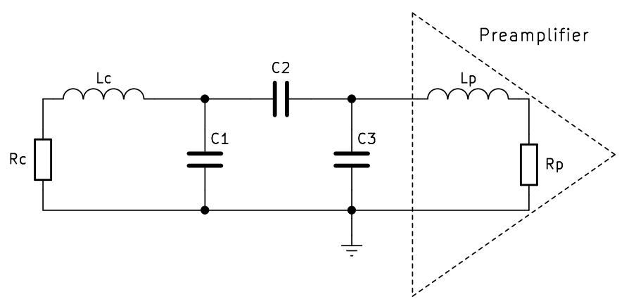
The principle of decoupling achieved by the matching circuits, described by Roemer et al. 1 and Reykowski et al. 2, is that a parallel resonance is created with an inductor such that a high impedance is presented to the coil. Hence impeding the current on the coil. An example of the parallel matching circuit is shown in Figure 1, where decoupling is achieved when C1 resonates with the equivalent impedance of C2, C3, Lp and Rp thus forming a parallel resonance. In the lossless case, this parallel resonance exhibits an infinite Q-factor when the preamplifier has a zero input resistance. Given that the resistance of the preamplifier is increased the Q-factor of the parallel resonance is lowered, the equivalent impedance is also lowered, more current is able to flow in the coil and thus a worse decoupling entails. In the case of a lossy matching circuit a zero resistance preamplifier does not yield an infinite Q-factor of the parallel resonance. To achieve the ideal decoupling the loss of the matching circuit can be compensated. The loss compensation is realized by an NIRP with a specific negative resistance such that the impedance seen by the coil is, theoretically, infinite.
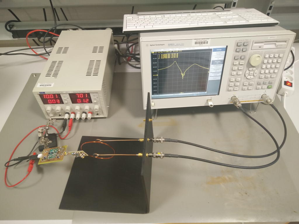
The decoupling is measured using a system of two small loop coils of 1 cm diameter separated by a distance of 4 cm connected to a vector network analyzer as seen in Figure 2. A parallel matching circuit, including active transmitter detuning, is used as presented by Sanchez-Heredia et al. 3. The coil is an 8 cm loop coil with an unloaded Q-factor of approximately 350 at 32.13 MHz, corresponding to the frequency of 13C at 3T. The NIRP is a custom design (based on the design presented by Johansen et al. 4) where the input impedance can be tuned while the noise figure remains constant at approximately 0.5 dB.
Results
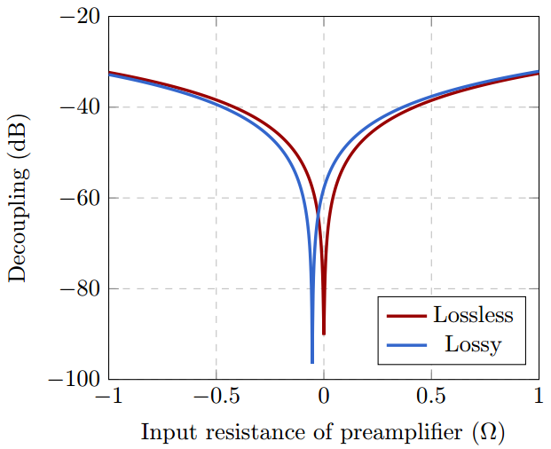
Figure 3 shows the simulated decoupling as a function of the input resistance of the preamplifier. It is seen that the optimal resistance is zero for the lossless case as expected. For the lossy case the optimal resistance is negative. For higher resistances the decoupling converges for the two cases. The measured decoupling as a function of frequency is plotted in Figure 4 for four different resistances of the preamplifier. As expected, the optimal decoupling is found when a small negative input resistance (-0.023 Ω) of the preamplifier is used resulting in a decoupling of -62 dB at 32.13 MHz.Discussion
The bandwidth of the decoupling is fairly narrow and the very high decoupling reported here is only at a single frequency. Since the bandwidth of the MRI experiment is in the range of 50-100 kHz this poses an issue. Theoretically it is possible to design a NIRP which exhibits an input impedance that yields a wider bandwidth. However, for this work, we have focussed on showing the principle of loss correction rather than increasing the bandwidth of the decoupling.Conclusion
We have presented the concept of loss correction to achieve, in theory, a perfect element decoupling for receive coil arrays in MRI. The implication is that a negative input resistance preamplifier (NIRP) is required to reach the perfect decoupling. This is because the loss of the matching circuit must be compensated. Measurements confirm the hypothesis, showing an optimal decoupling of -62 dB with a preamplifier input resistance of -0.023 Ω. Further work involves demonstrating the decoupling during different load conditions.Acknowledgements
This work was supported in part by the Danish National Research Foundation under grant DNRF124.References
1. Roemer, P. B., Edelstein, W. A. & Hayes, C. E. The NMR Phased Array. Magn. Reson. Med. 225, 192–225 (1990).
2. Reykowski, A., Wright, S. M. & Porter, J. R. Design of Matching Networks for Low Noise Preamplifiers. Magn. Reson. Med. 33, 848–852 (1995).
3. Sánchez-Heredia, J. D., Hansen, E. S. S., Laustsen, C., Zhurbenko, V. & Ardenkjaer-Larsen, J. H. Decoupling Scheme for a Cryogenic Rx-Only RF Coil for 13C Imaging at 3T. Proc. Intl. Soc. Mag. Reson. Med. 3639 (2016).
4. Johansen, D. H., Sanchez-heredia, J. D., Zhurbenko, V. & Ardenkjær-larsen, J. H. Practical Aspects of Preamplifier Designs for 13C Imaging. in Proc. Intl. Soc. Mag. Reson. Med. (2017).
Figures