1710
300 W Modified Class-E RF Amplifiers for 64 MHz Transmit Array System1Department of Electrical and Electronics Engineering, Bilkent University, Ankara, Turkey, 2National Magnetic Resonance Research Center (UMRAM), Ankara, Turkey, 3ValoTec,Engineering Consultant, Paris, France
Synopsis
In this work, highly efficient 300 W digitally controlled supply-modulated Class-E amplifiers for two-channel RF transmit array are presented. Load pull analysis is performed for load optimization purposes. Coupling between the transmit coils is measured to be 8% when 12 cm diameter coils are placed with a distance of 7 cm. The performance of amplifiers while working simultaneously at same frequency and at different frequencies is evaluated. MR experiments are conducted and it is observed that MR images show no artifact in the presence of amplifier near transmit coil inside the scanner.
Introduction
The aim of this research is to replace the low efficiency RF amplifiers used in conventional MRI systems with highly efficient on-coil array of switching amplifiers. Earlier, an on-coil class-D amplifier design was proposed in order to address this issue1,2. We presented a class-E amplifier as an alternative previously3 but no MR experiments were conducted. In this work, we improved the amplifier design and tested it for a two-channel RF transmit array system on a 1.5 T scanner. Load pull analysis was done for load optimization purposes. The coupling and performance of both amplifiers while working simultaneously were evaluated. MR experiments were conducted to check the behavior of amplifiers inside the scanner.Methods
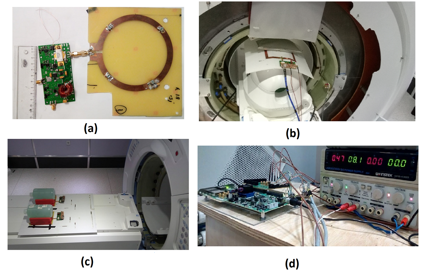
The class-E amplifier3-6 is modified to drive a 300 W LDMOS RF power transistor (Ampleon, BLF573, Nijmegen, The Netherlands). The supply modulation block is implemented with a half-bridge topology followed by a low-pass LC-filter. A 12 cm diameter coil tuned with 4 distributed capacitors is connected directly to the amplifier board, serving as the transmit coil as well as the tuning network of the amplifier (Fig.1a).
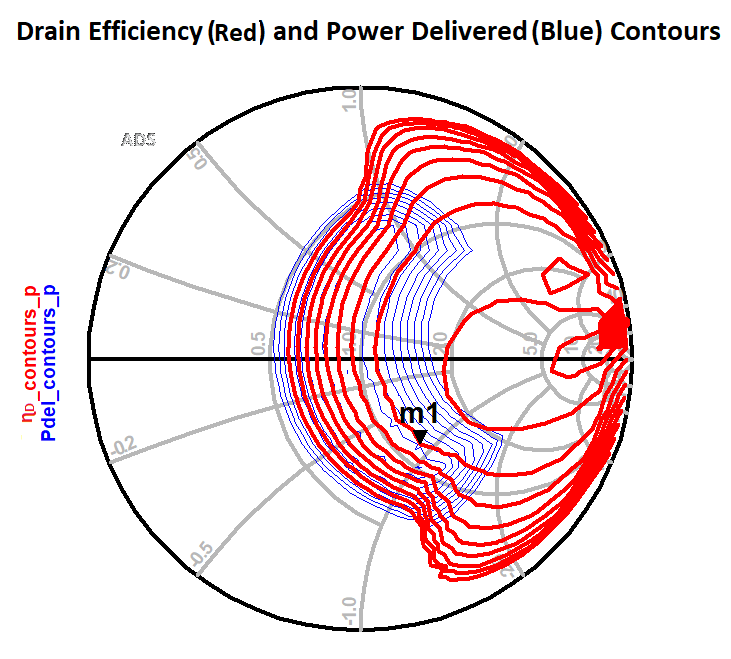
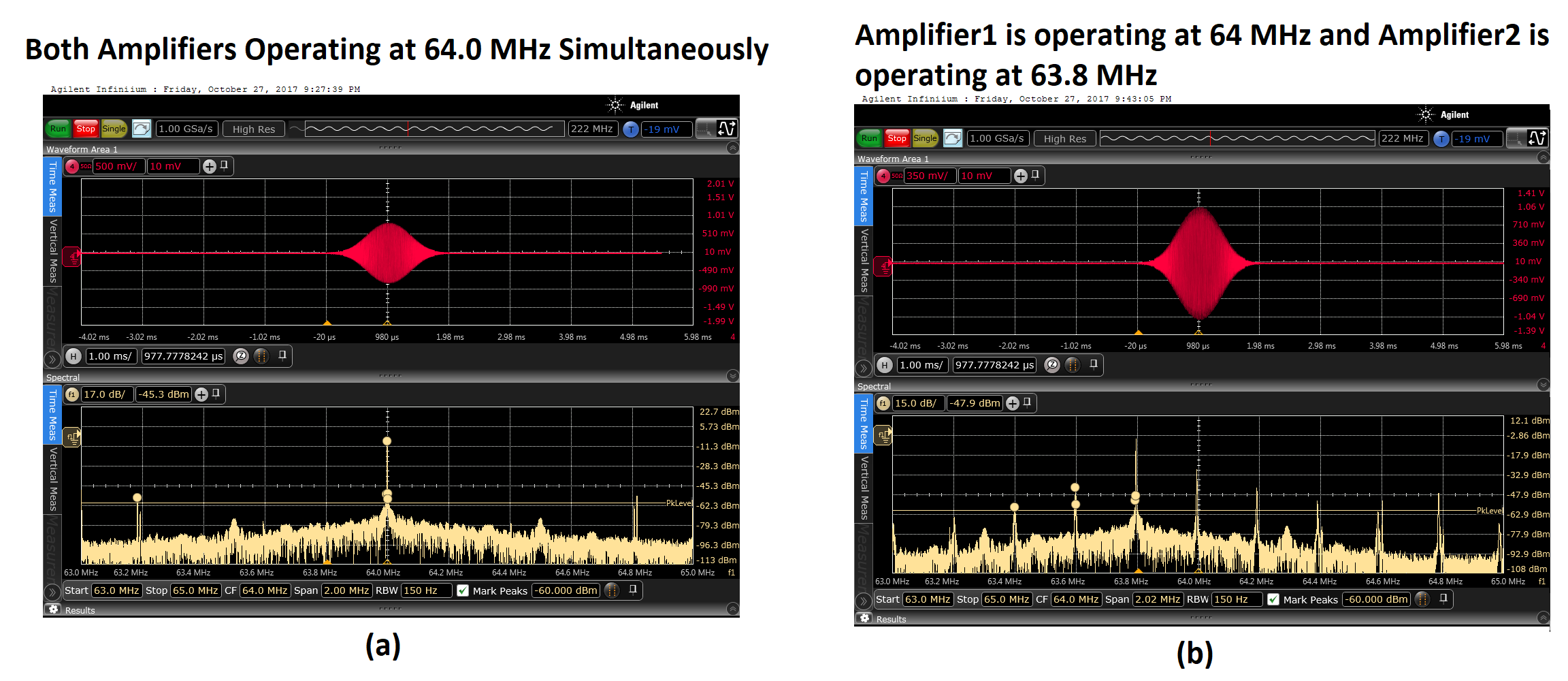
Load pull analysis is performed in ADS 2016 (Keysight, Santa Rosa, CA). The amplifier is simulated with a constant available source voltage while the load reflection coefficient is swept to find the best tuning point so that the amplifier can deliver 300 W power with maximum efficiency. The behavior of two amplifiers working simultaneously is also analyzed. It is anticipated that when two amplifiers are placed together, the inductance of transmit coil will change, and therefore, its tuning point will be shifted. This may cause the output pulse to distort and the efficiency to decrease. In order to test the severity of this effect, we tuned and decoupled the 12 cm diameter transmit coils at 64 MHz at 7 cm distance by altering the tuning capacitors on the transmit coil. After tuning, the behavior of both amplifiers was recorded when both of them were operating at same frequency and also at different frequencies.
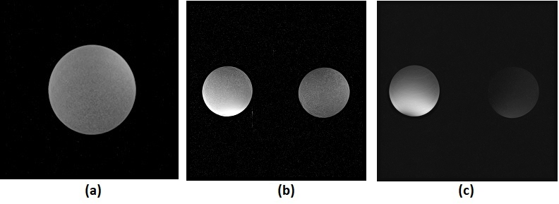
Two MR experiments were conducted in 1.5 T (Scimedix Inc., Incheon, South Korea). First experiment was performed with a single amplifier (Fig.1b). The second experiment was performed with two amplifiers to check the coupling (Fig.1c). In experiments, a KCU105 FPGA evaluation board (Xilinx Inc., California, USA) and power supplies were placed in the system’s room as shown in Fig.1d. The FPGA was given 63.8 MHz (the central frequency of Scimedix 1.5 T) and unblank signals from the scanner. The amplifier signals were given by the FPGA by LVDS signaling though a CAT7 ethernet cable. A 2 ms sinc pulse was used for excitation with TE/TR=15/200 ms.
Results
From the simulation results of load pull analysis, drain efficiency and power delivered at different load impedances were calculated. It was observed that when the transmit coil impedance is 1.2-j0.89 Ω, drain efficiency is 92% and output power is 54.8 dBm. Drain efficiency contours and power delivered contours are shown in Fig.2.
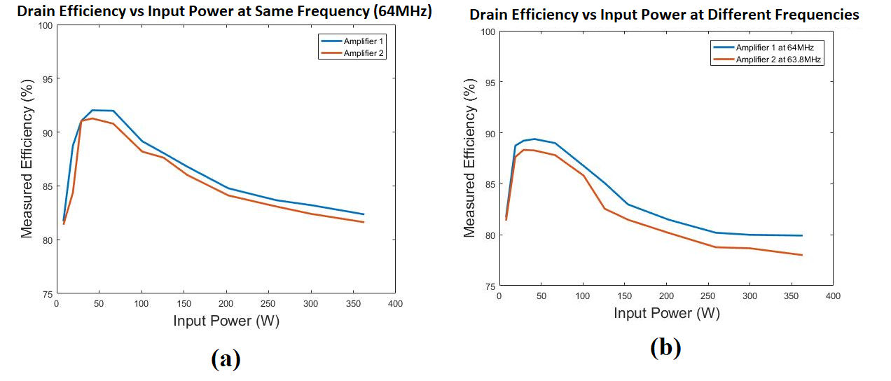
Coupling
between the transmit coils is measured to be 8% when 12 cm diameter coils are
placed with a distance of 7 cm. The
measured efficiency vs input power of both amplifiers after tuning is shown in
Fig.3.
The modulated output pulse and its FFT for amplifier1,
when both amplifiers work simultaneously at same frequency and at different
frequencies are shown in Fig.4. The MR
experiment results are shown in Fig.5.
Discussion
Our results show that in order to maintain the operation of the class E amplifier in the efficient region, there are some design constraints for the transmit coil. The tuning of coil is crucial for maximum output power and high efficiency as coil itself is used for matching and tuning network and a separate matching network is not required. The behavior of the class-E amplifiers under coupled operations is being investigated. The initial results show that the effect is tolerable. The MR images show no artifacts in the presence of amplifier near the transmit coil inside the scanner.Conclusion
Class-E amplifier has proven to be a good candidate for on-coil application. It has potential to replace the conventional MRI RF amplifiers because of its small size and high efficiency capability without the need for additional cooling system. The ultimate goal of this research is to design a 32-channel transmit array using on-coil amplifiers that will be able to deliver 300x32=9.6 KW power which should be sufficient to run the body coil on a 1.5 T MR scanner.Acknowledgements
No acknowledgement found.References
1. Gudino N, Heilman JA, Riffe MJ, Heid O, Vester M, Griswold MA. On-coil multiple channel transmit system based on class-D amplification and pre-amplification with current amplitude feedback. Magn Reson Med 2013;70:276–289.]
2. Gudino N, Duan Q, de Zwart JA, Murphy-Boesch J, Dodd SJ, Merkle H, van Gelderen P, Duyn JH. Optically controlled switch-mode current-source amplifiers for on-coil implementation in high-field parallel transmission. Magn Reson Med 2016;76:340–349.
3. Zahra, F.T., Silemek, B., Poni, R., Ashfaq, B.N. and Atalar, E., A Highly Efficient 250 W Digitally Controlled Supply-Modulated Modified Class-E Amplifier for on-Coil Implementation in 1.5T MRI, ESMRMB, Barcelona, Spain, 2017
4. Poni, R., MS.Thesis:A Digitally Controlled Class E Amplifier for MRI, Bilkent University,2016.
5. Poni, R., Demir, T. and Atalar, E., A Digital Power Amplifier for 1.5 T, ISMRM, Toronto, Canada, 2015
6. Poni, R., Silemek, B., Gundogdu, U., Demir, T., Ertan, N.K. and Atalar, E., Modified Class E Amplifiers Used For Two Channel Digital RF Transmit Array System With Integrated Coil, ISMRM, Singapore, 2016
Figures