1708
A 12-Channel Degenerate Birdcage Body Transmit Array Coil for 1.5T MRI Scanners1Electrical and Electronics Engineering, Bilkent University, Ankara, Turkey, 2National Magnetic Resonance Research Center (UMRAM), Bilkent University, Ankara, Turkey, 3Aselsan, REHIS Power Amplifier Technologies, Ankara, Turkey
Synopsis
In this work, we designed and manufacture a 12-channel body birdcage degenerate transmit array coil. After determining the size of the coil, the trace thickness for each of the conductors and the location of the capacitors, an EM solver is used to find the equivalent circuit model of the coil. The capacitor values are tuned by solving the circuit model and recalculating the EM model iteratively. After reaching the minimum total reflection of 14%, we constructed the 12-channel body degenerate birdcage transmit array coil. The strongest coupling was observed between adjacent channels measuring as -15.7 dB.
Introduction
Although use of the transmit array (TxArray) technology is widely tested for ultra-high field system, we believe it can be very useful for the 1.5T scanners as well. For example, it was shown earlier that the heating due to the elongated metallic structures in the body such as the leads of the active implantable medical devices can be reduced when this technology is used1. On the other hand, designing a TxArray coil is much more difficult than designing a conventional coil due to the coupling between its channels. Hence, having an equivalent circuit, which can accurately model the electrical performance of the TxArray coil loaded with a sample, might be useful in the design process.
Different studies attempted to model TxArray coils under the assumption that the coupling between the non-adjacent channels is negligible2-4, however, for an array coil with a large number of channels, the coupling between non-adjacent channels becomes significant. In addition, the loss in the coil elements need to be quantified in order to accurately estimate the capacitor values for such coil.
In this study, we modified the equivalent circuit model of a conventional birdcage coil5 for multi-element array coils by considering all of the self/mutual-inductors as magnetic coupling and self/mutual resistors as electric coupling. We introduced an iterative method to determine value of model parameters. Using the calculated values of the capacitors, we constructed a shielded 12-channel degenerate birdcage body transmit array coil.
Methods
Fig. 1 shows the general structure and the equivalent circuit model of a shielded degenerate birdcage TxArray coil. In the proposed model, the effects of all self/mutual-inductors and self/mutual-resistors originating from the coil, its shield, and subject (a cylindrical object with uniform conductivity and dielectric constant) are considered. The current on an element of the coil can induce the eddy currents on the subject. These eddy currents can induce electromotive force on other elements of the coil. This effect can be modeled as a mutual-resistor5.
By analyzing the model of N-element TxArray coil with the Kirchhoff mesh current method a linear system with 2N-equations is created. These equations can be used to derive the impedance (Z) or scattering (S) matrices of the model as function of model parameters and frequency. If we can find a method to estimate all of the model parameters, S-matrix of the model can be determined for all the frequencies.
The self/mutual-inductor values can be estimated theoretically
using the Neumann formula6 and for low (≤3T) fields, they are depending only on the coil’s
geometry. In addition, setting
some reasonable initial values for the capacitors and performing the simulation
of the array coil using an EM solver can extract S-matrix.
It can be shown that if S-matrix, capacitor and self/mutual-inductor
values be known, then self/mutual-resistor values can be calculated for all
frequencies. For a given geometry, the resistor values depend on the capacitor
values, however we ignored this dependency in each of the iterations. Since all
of the inductor and resistor values are known, S-matrix obtained from
the model can be optimized by adjusting capacitor values. The error function (EF) is
defined as the 2-norm of the S-matrix due to the for a given set of
capacitor values (\(\overline{\textbf{c}}\)), EF=\(\lVert\textbf{S}(\overline{\textbf{c}})\lVert\).
Minimizing
EF at the operating frequency increases the total power deposited in the
coil/phantom. In order to solve the minimization
problem, and find the new values for the capacitors, the steepest-descent
method7 is used. By updating
the values of capacitors and re-simulate of the array, the new S-matrix can be extracted. Then,
capacitors values should be readjusted to optimize EF (Fig. 2). Repeating the mentioned
procedure for less than three times to reduces the error in resistor values,
will enable us to design a multi-channel birdcage array coil.
Results and discussion
As proof of the method, a shielded 12-channel birdcage body transmit array coil developed and constructed (Fig. 3). Four capacitors are optimized as explained in the methodology so, the coil is matched to 50Ω and tuned to 63.8MHz.
Fig. 4 illustrates the simulated and measured S-matrix of the loaded array coil, which shows all of the channels are matched and decoupled. These results are obtained by performing three iterations of the described method.
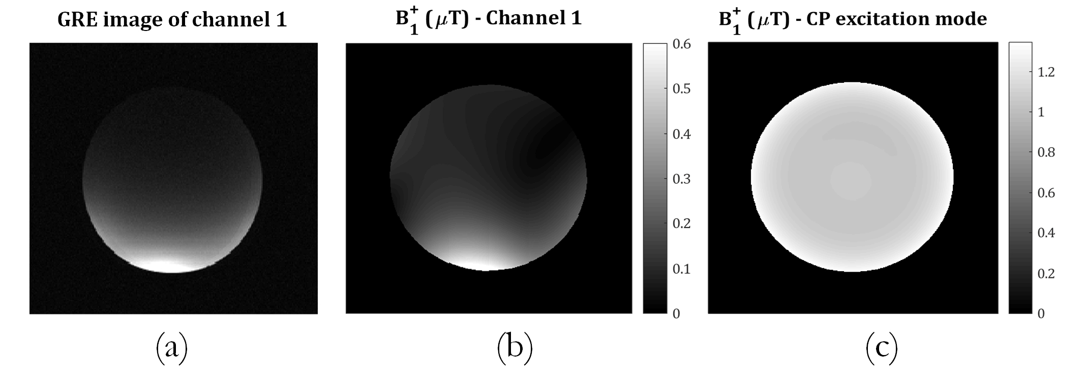
Fig. 5(a) represents the image acquired when only one channel of loaded coil is driven. Fig. 5(b-c) demonstrates simulated $$$B_1^+-map$$$ of an individual channels and when the coil is driven in the circular polarized mode.
Conclusion
To sum up, in this work we found the capacitor values for a degenerate birdcage body TxArray coil using a novel iterative method. We demonstrated the validity of the method by constructing a 12-channel degenerate birdcage body TxArray coil and measuring its performance.Acknowledgements
References
1. Eryaman, Y, Turk EA., Oto C, Algin O, and Atalar E, “Reduction of the radiofrequency heating of metallic devices using a dual-drive birdcage coil”, Magn Reson Med, 2013, 69:845-857.
2. Novikov A, “Advanced Theory of Driven Birdcage Resonator with Losses for Biomedical Magnetic Resonance Imaging and Spectroscopy”, Magn. Reson. Imaging 29, 2011, 260–271.
3. Sadeghi Tarakameh A, Kazemivalipour E, Demir T, Gundogdu U, Atalar E., “Design of a Degenerate Birdcage Radiofrequency Transmit Array Coil for the Magnetic Resonance Imaging Using Equivalent Circuit Model”, ESMRMB 2017, 34th Annual Scientific Meeting, Barcelona, ES, 2017, No: 316. MAGMA 2017; 30:S300–S301.
4. Avdievich NI, Pfrommer A, Giapitzakis IA, “Henning A. Analytical modeling provides new inside into complex mutual coupling between surface loops at ultra-high field”, NMR Biomed. doi:10.1002/nbm.3759.
5. Harpen MD, “Equivalent Circuit for Birdcage Resonators”, Magn. Reson. Med. 29, 1993, 263–268.
6. Grover FW, “Inductance calculations: working formulas and tables”, Courier Corporation, 2004.
7. Etminan A and Gurel L, “Microwave imaging of three-dimensional conducting objects using the Newton minimization approach”, Proc. Computational Electromagnetics Workshop, CEM’13, pp. 45–47, Izmir, Turkey, 2013.
Figures