1706
A Flexible Transceiver Array for Cardiac MRI at 7 T: Performance Evaluation on a Torso Phantom1IR4M (Imagerie par Résonance Magnétique Médicale et Multi-Modalités), Univ. Paris-Sud, CNRS, Université Paris-Saclay, Orsay, France, 2Division MR Physics - Center for Medical Physics and Biomedical Engineering, Vienna, Austria
Synopsis
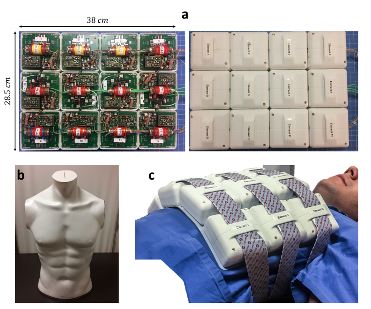
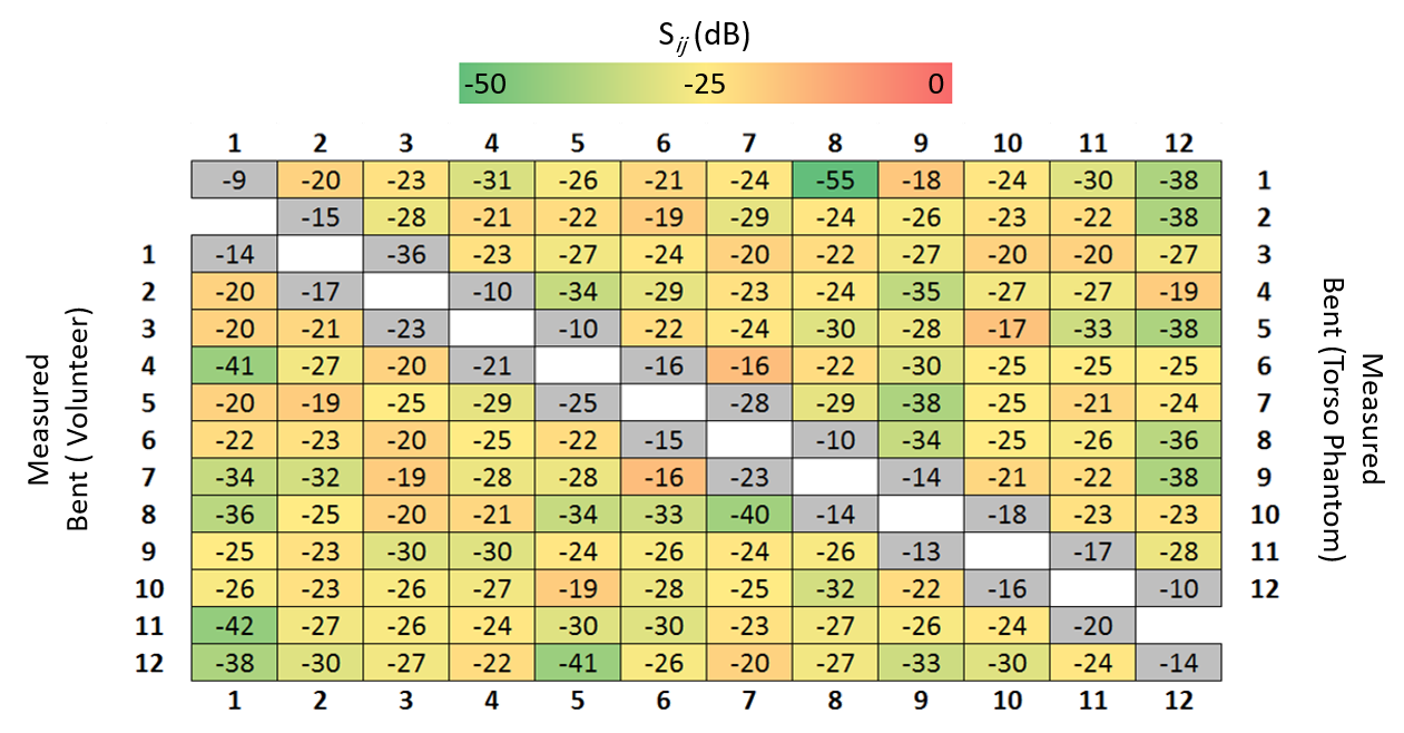
A flexible 12-channel transceiver transmission line resonator (TLR) array for 7 T cardiac 1H MRI compatible with parallel transmission systems was developed. The size of the array is 38 cm x 28.5 cm with individual TLRs of 84 mm diameter. A decoupling ring-based inter-element decoupling technique was used where the basic TLR geometry is surrounded by a conducting ring. Its efficiency was demonstrated with the array bent on a torso phantom and a human torso (Sij < -16 dB). Acceleration factors up to 3 in bent configuration can be employed without significant SNR degradation (g-factor < 1.6).
Purpose
Transmission line resonators (TLRs) can be used to develop mechanically flexible coil arrays. Flexibility improves geometrical conformity of the coil to the sample yielding a significant SNR gain in the receive mode and improved transmit efficiency1. In previous work, a flexible 12-element TLR array was developed using a decoupling ring-based technique2,3 and decoupling performance, transmit efficiency and imaging performance were evaluated in flat configuration4. In this work, we evaluate the performance of the developed array in bent configuration including decoupling and transmit efficiency together with parallel imaging performance using bench and MR measurements at 7 T.Methods
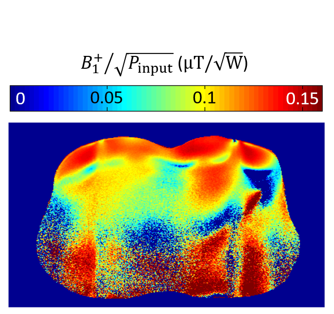
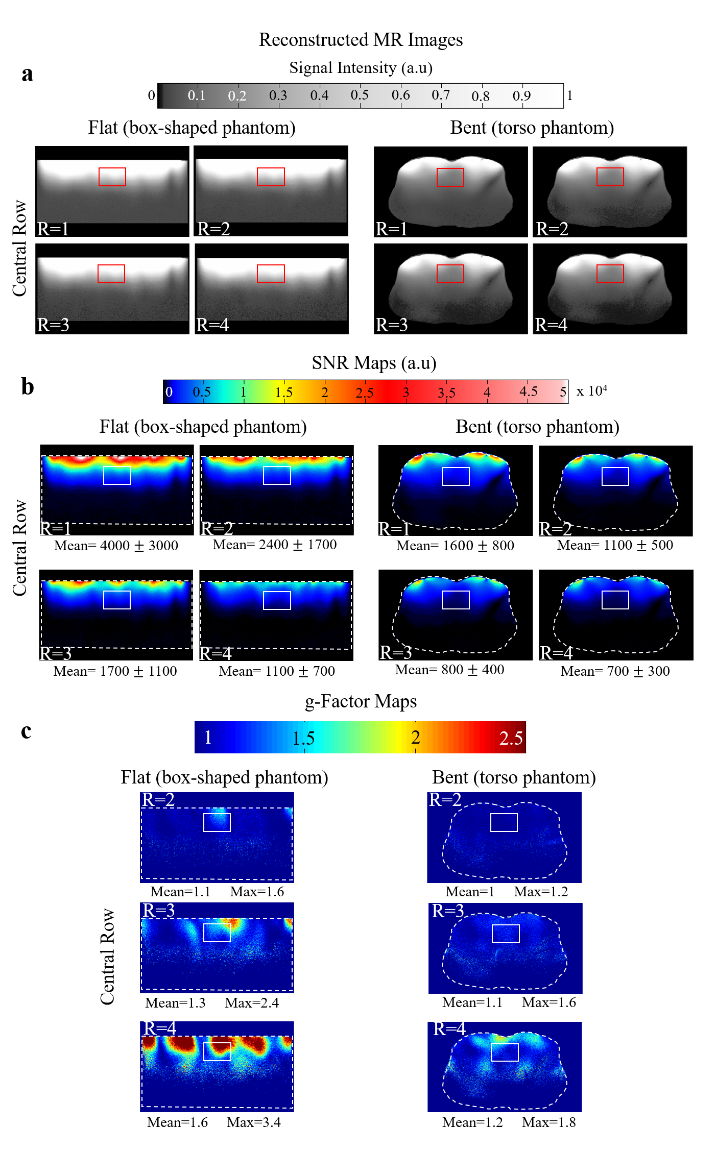
Figure 1a shows the design of the fabricated array. A flexible-rigid PCB technology was used, enabling the positioning of interfacing circuitry (power splitter, transmit/receive switch, preamplifier and capacitive tuning/matching network) while preserving the flexibility4. A static $$$B_1^+$$$ phase shimming algorithm5 was applied to achieve a tradeoff between maximum $$$B_1^+/\sqrt{P_{input}}$$$ and homogeneity on a flat phantom. This resulted in a 90° phase difference between each column of 3 equally phased coil elements. A torso phantom (Fig.1b) filled with tissue-like gel (σ = 0.60 S/m, ε = 62) was developed and used for bench and MR measurements. On bench, the S-parameter matrix was measured for two configurations: bent onto the torso phantom and bent on the torso of a volunteer (male, 30 years, body mass index = 28.4 kg/m2) as shown in Figure 1c. MRI experiments were carried out on a whole body MRI scanner (Magnetom 7T-MRI, Siemens Healthineers, Erlangen, Germany) in flat (rectangular-shaped phantom 64.5 x 44.7 x 11.6 cm3 filled with NaCl solution (σ = 0.53 S/m)) and bent (torso phantom) configurations. Flip angle maps were acquired using the Saturated Turbo FLASH method6, applying a slice-selective saturation pulse (2 ms duration, 100 V amplitude). $$$B_1^+$$$ maps normalized to the input power were calculated using measured flip angle maps. The parallel imaging performance of the developed array was investigated in flat and bent configurations using the pseudo-multiple replica technique7 and off-line GRAPPA reconstruction8. To calculate the noise correlation matrix, noise-only data were acquired using an FID sequence without excitation. Fully-encoded 2D GRE images (TR⁄TE =427/3.76 ms, nominal flip angle of 10°, 1.16 x 1.16 mm2 nominal resolution and 5 mm slice thickness) were acquired by placing a transversal slice in the central row of the array. Reconstructed 2D images, SNR and g-factor maps were calculated for acceleration factors R = 1 (no acceleration), R = 2, R = 3 and R = 4.Results
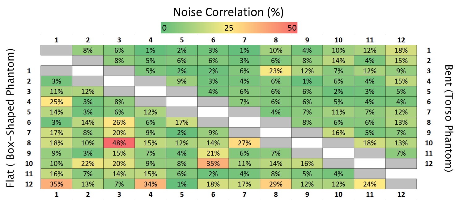
Figure 2 represents the S-parameter values of the developed array measured on the bench when the array was bent onto the torso phantom and the torso of the volunteer demonstrating decoupling levels (Sij) below -16 dB. Figure 3 shows the measured transversal $$$B_1^+/\sqrt{P_{input}}$$$ profile of the central row of the developed array in bent configuration. Figure 4 shows the noise correlation matrix for the array in flat and bent configuration on phantom, with a maximum of 48% and 23% in flat and bent configurations, respectively. Figure 5 shows the reconstructed MR images (Fig. 5a), SNR maps (Fig. 5b) and calculated g-factor maps (Fig. 5c) for different acceleration factors in flat and bent configurations on phantoms.Discussion
Measured scattering parameters, noise correlations as well as reconstructed images, SNR and g-factor maps proved the robustness of mechanical flexibility of the developed array. Noise correlation and g-factors in bent configuration are considerably lower than in flat configuration and acceleration factors up to 3 were possible without significant degradation in SNR. Static $$$B_1^+$$$ shimming could be improved by optimizing phases for an average bent configuration.Conclusion
A flexible 12-element transceiver array for 7 T MRI based on TLRs was successfully implemented and tested. The developed array enables coil conformity for samples with various sizes to increase detection sensitivity in MR experiments. The fabricated array is compatible with parallel imaging and pTx techniques yielding accelerated imaging and dynamic $$$B_1^+$$$ shimming. The flexible array targets cardiac MRI for which form-fitting can be advantageous since human torso size varies from patient to patient. Future work aims at combining the 1H array with an 31P array for cardiac 31P MRS at 7 T. Furthermore, it is envisioned to increase the number of channels by developing another 1H array that will be placed on the back of the human torso extending the coverage of the array with improved transmit efficiency and receive sensitivity in depth.Acknowledgements
Austrian/French FWF/ANR programme Blanc grant, Nr. I1371-B24, “FLEXAR7” Austrian/French OeAD/MAEE projects WTZ/PHC Amadée FR10/2015References
[1] Kriegl R et al., Magn Reson Med 73(4):1669–1681, 2015.
[2] Lanz T et al., ISMRM 2006, p.217.
[3] Li Z et al., ESMRMB 2015, p.74.
[4] Hosseinnezhadian S et al., ESMRMB 2017, p.299.
[5] Goluch et al., Magn Reson Med 73: 2376-2389, 2015.
[6] Chung S et al., Magn Reson Med 64: 439-446, 2010.
[7] Robson et al., Magn Reson Med 60: 895-907, 2008.
[8] Breuer et al., Magn Reson Med 62: 739-746, 2009.
Figures