1704
Fixed-phase prostate imaging with a 8-channel transmit/receive dipole antenna array on a conventional 3T systemAidin Ali Haghnejad1, Mark Gosselink1, Ingmar Voogt1, Dennis Klomp1, Peter Luijten1, and Alexander Raaijmakers1,2
1Radiology, UMC Utrecht, Netherlands, Utrecht, Netherlands, 2Eindhoven University of Technology, Biomedical Image Analysis, Eindhoven, Netherlands
Synopsis
Local multi-transmit arrays at 3T provide reduced power requirements and reduced local SAR. However, it requires 3T scanners with multi-transmit functionality which are rare. This work presents add-on hardware that enables the use of local transmit/receive arrays. An exploration on prostate imaging with fixed phase settings using a 8-channel dipole array has been performed on four subjects. B1+ levels range from 5 to 8.5 uT for 8 x 215-300 W input power. T2w images have been acquired successfully for each subject. The modest inter-subject variation in B1+ demonstrates the feasibility of this approach.
Purpose
The birdcage body coil provides superior B1+ homogeneity for MR imaging at both 1.5 and 3T. However, the use of local multi-transmit arrays at 3T has demonstrated considerable advantages in terms of reduced power requirements and reduced local SAR1. This approach requires a so-called multi-transmit system where the phases of all channels can be independently controlled. Currently only very few 3T MRI systems have this functionality. In this work we present add-on hardware to perform multi-transmit MR imaging at a conventional 3T system using a local transmit/receive array. With this setup, prostate imaging performance is explored for a 8-channel meandering dipole array using fixed phase settings.Methods
Two 4-channel power dividers have been built using LC circuits (figure 1E). The resulting eight channels are connected to eight custom built transmit/receive switches (figure 1C). A 8-channel transmit/receive array1 was used consisting of dipole antennas of 30 cm length where half of each leg of the dipole antenna was meandering with 30 cm width and 2 meanders per cm (figure 1D). A lattice balun ensured matching and differential drive. Local SAR distribution was determined using numerical simulations (Sim4Life, Zurich Medtech). Maximum 10g-averaged local SAR for 8x1 W input power was determined at 2.2 W/kg (figure 2). This resulted in a maximum average input power of 9.1 W per channel. The two input channels of the power dividers were connected to the two disconnected cables to the body coil of a 3T Ingenia system (Philips Healthcare, Best, The Netherlands). The allowed peak power arriving at the power divider for this study was 1200/1400 W for channel 1 and 2 respectively. This resulted in 215 to 300 W power arriving at the TR-switch coil connector. The receive lines of the TR-switches were connected to a D-stream box (MR Coils B.V., Zaltbommel, The Netherlands) that connects to the receive interface of the scanner. Optimal phases were obtained for one subject through addition of appropriate cable lengths, determined by single-channel phase images. To investigate the feasibility of one fixed cable length setup for multiple subjects, three other subjects were scanned with the same cable lengths and B1+ levels in the prostate were recorded. In addition, T1w and T2w images were acquired for each subject.Results and discussion
The B1+ levels acquired in the prostate with the dipole array are indicated in table 1. On average, 6.6 uT is obtained. Figure 3 shows T1w images for all subjects. The B1+ levels in the prostate vary and are generally low but no signal dropout is ever observed inside the prostate for any subject. This combined with the relatively low input powers enables the compensation of lower B1 levels by higher input power similar to the way that input power to the body coil is optimized before every scan. Figure 4 shows T2w images for each subject showing that good quality images can already be obtained with this setup. However, in absence of a dedicated receive array, the image quality should not be compared to state-of-the-art image quality for prostate imaging at 3T.Conclusion
Dedicated add-on hardware was developed to allow the use of local multi-transmit coil arrays at a conventional 2-channel 3T system. Using one optimized phase setting (acquired through additional cable lengths) B1+ values in the prostate ranged from 5 to 8.5 uT for four different subjects using 8 x 215-300 W input power. Future work will focus on exploring 2-channel RF shimming for B1+ improvement and adding in a comparison to a transmit/receive loop coil array.Acknowledgements
This project is funded by STW project nr: 13783
References
1. A. Haghnejad, in Proceedings of the ISMRM 24th Annual Meeting 2016, #3174Figures
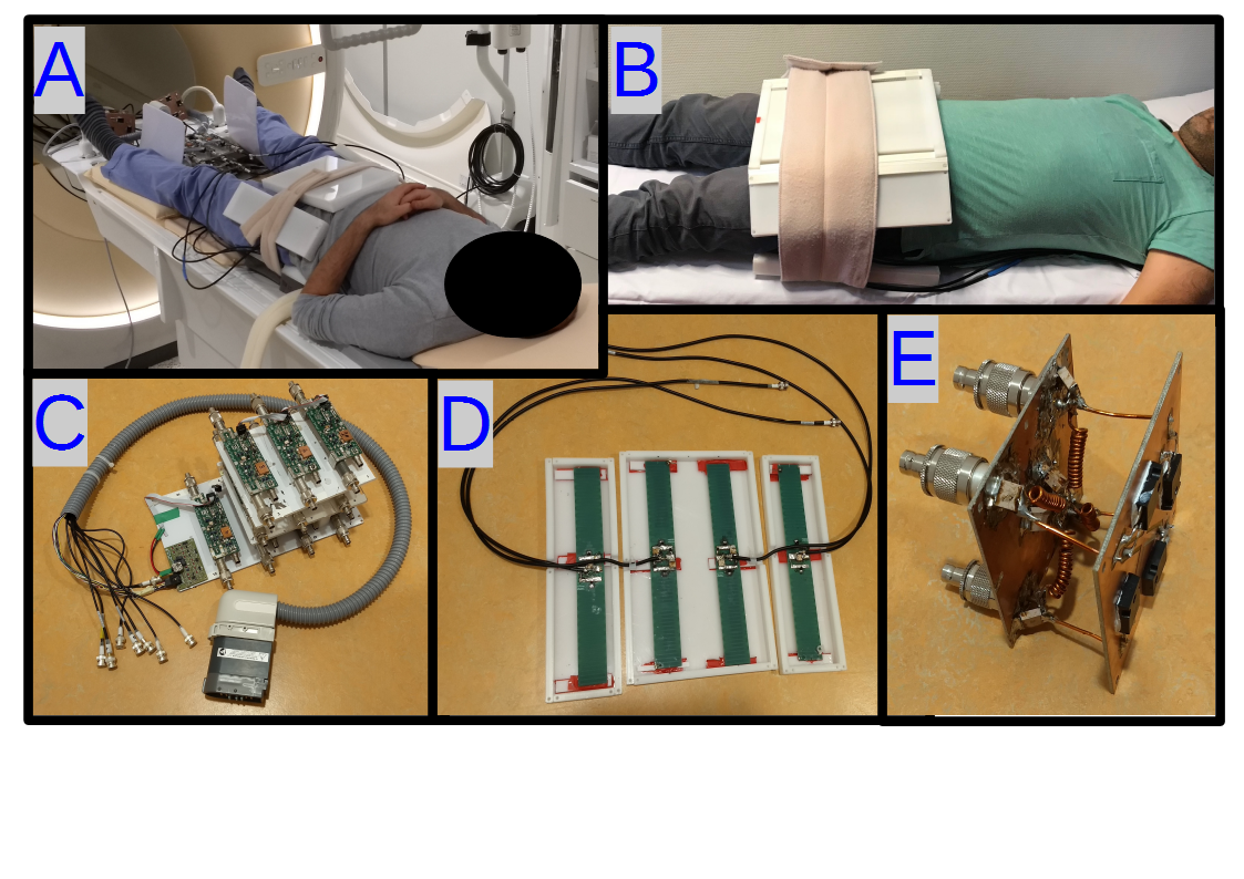
Figure 1: A,B) imaging setup, C)
transmit/receive switches with cable interface to Dstream box D) Dipole antenna
array (anterior side). E) 4-channel power divider.
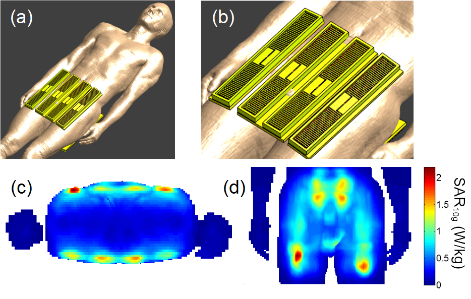
Figure 2: a and b) Simulation setup. c and
d) SAR distribution based on sum-of-magnitude electric fields (maximum possible
SAR distribution).
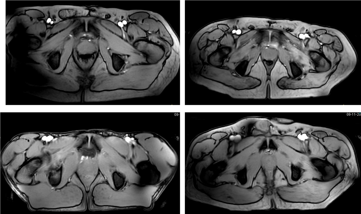
Figure 3: T1w images for four investigated
subjects showing relatively homogeneous intensity distribution (FA 30°, TR/TE=80/3.9 ms, 1x2x10 mm3)
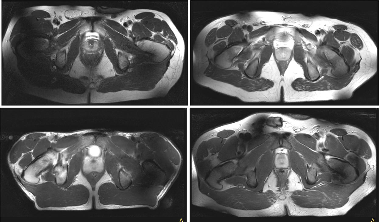
Figure 4: T2w images for four investigated
subjects (TR/TE=7000/70 ms, 1x1x5 mm3, TSE-factor 17)

Table 1: B1+ level in the prostate for each imaging subject