1703
Strip transmission line RF coil combined with RF shielded PET detector for existing MRI systems1National Institute of Radiological Sciences, Japan, Chiba, Japan
Synopsis
PET insert for the existing MRI systems can be a potential affordable alternative of body PET/MRI system. To avoid mutual interference between PET front-end electronics and the MRI system, PET front-end (F/E) electronics are enclosed in RF shielded Faraday cage that is connected to the RF ground for shielding purpose. On the other hand, strip transmission line RF coil requires a grounded plane in parallel with a strip conductor as coil that are connected by shunt capacitors. In this study, we proposed a strip transmission line coil that replaced the ground one layer conductor with the shielded PET detector module. The combined system shows promise for a compact PET/RF coil modality as insert for simultaneous PET/MR imaging with existing MRI systems, suitable even at ultrahigh field MRI.
Introduction
PET insert for the existing MRI systems can be a potential affordable alternative to the body PET/MRI system. Studies on PET inserts concentrated on developing RF-shielded PET-ring in which a loco-regional RF transmit (Tx) coil was used inside the PET-ring [1] or integrated with the PET-ring [2-3] or the MRI built-in body RF coil was used as transmitter [4]. In the case of receiver coil (Rx), the same Tx coil or a separate Rx coil was used in those studies. Recent studies reveal the development of a dedicated multichannel Rx coil [5] for PET insert to increase receive sensitivity and at the same time to implement state-of-the-art parallel imaging for accelerated MRI performance.
Most of the works on human PET inserts are concentrated on brain imaging using existing 3 Tesla MRI systems. The 7 T MRI system is now commercially available that surely increases the SNR values to a greater level. As the proton precession-frequency increases with the value of magnetic field, the wavelength of the transmit RF-field become comparable to the human organ dimension that creates constructive and destructive interferences of RF-field inside the imaging region [6-9]. As a result, maintaining transmit RF-field homogeneity becomes challenging by using conventional volume RF coils (e.g., birdcage coil) [8-9]. Different research efforts on developing multichannel transmission line RF coil have been proposed [7-9]. In a target to develop PET insert for the 7T MRI system, we are working on the development of multichannel Tx/Rx type strip transmission line RF coil combining RF shielded PET detector module. At present we developed a one-channel coil for 3T MRI system.
In the case of strip transmission line coil with primary harmonics, two shunt capacitors are connected at two-ends in between the strip conductor and a wider ground-plane. On the other hand, in case of PET inserts for MRI, the shielded PET detector modules are connected to the RF ground for shielding purposes. We proposed to replace the ground plane of the strip transmission line coil with RF-shielded PET module that are connected by shunt capacitors for coil design purpose.
Materials and Methods
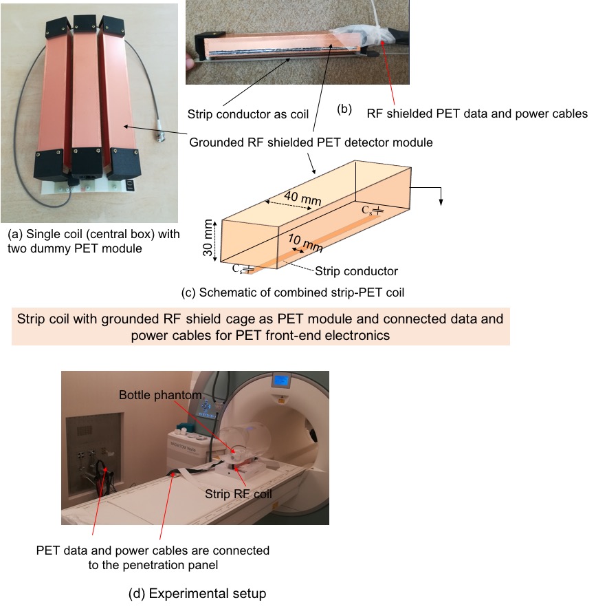
As a primary test, we developed two separate single channel strip transmission line coils – one with one layer grounded plane (conventional) and another one with grounded PET detector module for comparison, as illustrated in Fig. 1. Two shunt capacitors were used in between strip conductor and ground plane/grounded PET module [7]. Fixed ceramic capacitors of value 10pF and trimmer capacitor (1-16pF) were used as shunt capacitors for tuning the coil. A trimmer capacitor in between the coil and T/R switch was used for matching to 50-ohm. 35 micro-meter-thick copper was used as conducting/shielding materials.
At present, we tested for air gap in between the strip conductor and grounded shield, since using dielectric materials might attenuate the PET gamma rays. The width of the strip conductor was 10-mm and ground plane/PET module was 40-mm, and the gap in between was 10-mm (Fig. 1(c)). As a shielded PET detector module, we used a Faraday shield cage of dimensions 250-mm X 40-mm X 30-mm. The coil axial-length was 250-mm.
For both strip conductor and PET module, usual RF shielded PET data and power cables for the PET detector modules were connected to the PET module to mimic more practical scenario, Fig. 1. The coil tuning was performed after connecting cables to the PET module. S-parameters were studied using a Network analyzer (Rohde & Schwerz). A 15-mm diameter pickup coil was used to check the RF-field inside the Faraday cage.
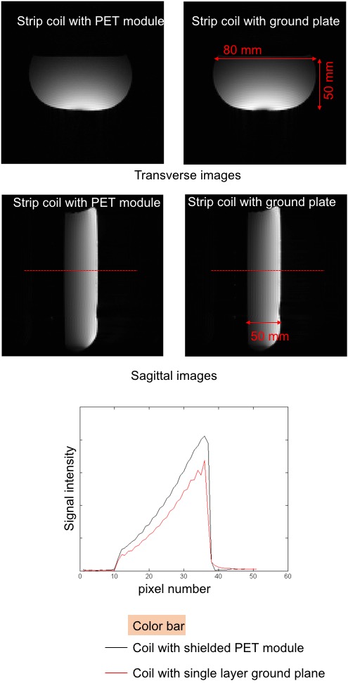
All experiments were conducted in a 3T clinical MRI system (Siemens MAGNETOM Verio) with a small bottle phantom filled with distilled water. The length and width of the bottle was 150mm and 80mm, respectively. Experimental setup is shown in Fig. 1 (d). The distance between coil and phantom was 15mm. Gradient-echo images were taken for TR = 200ms, TE =5ms, flip-angle= 600, Slice-thickness= 5mm, FOV for transverse plane= 125mm and for sagittal plane= 200mm.
Results and Discussion
The S11 parameter for both coils were about -30 dB. A 15-mm diameter pickup coil was used to check the RF-field inside the Faraday cage and the shielding effectiveness was about -45 dB. Gradient-echo images are given in Fig. 2 with a line profile comparing for the strip coil with ground plane and PET module. To avoid extreme brightening of the imaging region near the coil, we reduced the coil power from the value automatically generated by the MRI system. At present, we are working on the development of a 4-channel coil following this design. We hope to demonstrate details of the 4-channel coil performance along with PET detector performances in ISMRM annual meeting.Acknowledgements
No acknowledgement found.References
[1] A. Kolb, et al., Technical performance evaluation of a human brain PET/MRI system, Eur. Radiol. 22 (2012) 1776–1788;
[2] F. Nishikido, et al, Development of a full-ring “add-on PET” prototype: A head coil with DOI-PET detectors for integrated PET/MRI, Nucl Instr Meth Phy Res A 863 (2017) 55–61;
[3] M.S.H Akram, et al, MRI compatibility study of an integrated PET/RF-coil prototype system at 3 T, Jour Magn Reson, 283 (2017) 62–70;
[4] P. Olcott, et al., Prototype positron emission tomography insert with electro-optical signal transmission for simultaneous operation with MRI, Phys. Med. Biol. 60 (2015) 3459–478;
[5] C.Y Sander, et al, A 31-Channel MR Brain Array Coil Compatible with Positron Emission Tomography, Magn. Reson. Med., 73:2363–2375 (2015).
[6] C.M. Collins, et al, Central Brightening Due to Constructive Interference With, Without, and Despite Dielectric Resonance, Jour. Magn, Reson. Imag. 21:192–196 (2005).
[7] R.F. Lee, et al, Lumped-Element Planar Strip Array (LPSA) for Parallel MRI, Magn. Reson. Med. 51:172–183 (2004).
[8] G. Adriany, et al, Transmit and Receive Transmission Line Arrays for 7 Tesla Parallel Imaging, Magn. Reson. Med. 53:434–445 (2005).
[9] G. Adriany, et al, A 32-Channel Lattice Transmission Line Array for Parallel Transmit and Receive MRI at 7 Tesla, Magn. Reson. Med. 63:1478–1485 (2010).
Figures