1702
Small self-decoupled RF coils1Institute of Imaging Science, Vanderbilt University, Nashville, TN, United States, 2Department of Radiology and Radiological Sciences, Vanderbilt University, Nashville, TN, United States, 3Department of Biomedical Engineering, Vanderbilt University, Nashville, TN, United States
Synopsis
The self-decoupled coil that is intrinsically decoupled proves to be a simple way to solve coupling issues in RF arrays. Small mode capacitances are needed to balance the dipole- and loop-mode coupling in self-decoupled coils, which then requires the addition of inductors to maintain the resonant frequency. But inductors may lead to loss and thus decrease transmit efficiency. In this work, we investigated the performance of small self-decoupled coils at 7T and compared it to ideal conventional coils. It was found that the coil performance of self-decoupled array could be well preserved so long as the sample loss is dominated. Based on these simulation and experimental results, the self-decoupled coil is a good candidate for dense coil arrays at ultrahigh fields.
Purpose
RF array coils1 are widely used for reception and excitation at ultra-high fields. Steady increases in the number of array elements have led to major advances in image encoding and high field imaging2-7, but complex coupling issues arise in dense arrays. The self-decoupled coil8 that is intrinsically decoupled proves to be a simple way to solve these problems. Small mode capacitances are needed to balance the dipole- and loop-mode coupling in self-decoupled coils, which then requires the addition of inductors to maintain the resonant frequency. But adding inductors may lead to losses and thus decreased transmit efficiency. In our initial self-decoupled coils of size 10x10 cm2, the total added inductance was 30 nH, which was negligible compared to the coil’s self-inductance (hundreds of nH). However, when the self-decoupled designs are used for denser arrays such as 32-ch or 64-ch head coils, the coil sizes could be as small as 5 cm and the inductor losses then may become more significant. In this work, we investigated the performance of small self-decoupled coils at 7T and compared them to ideal conventional coils.Methods
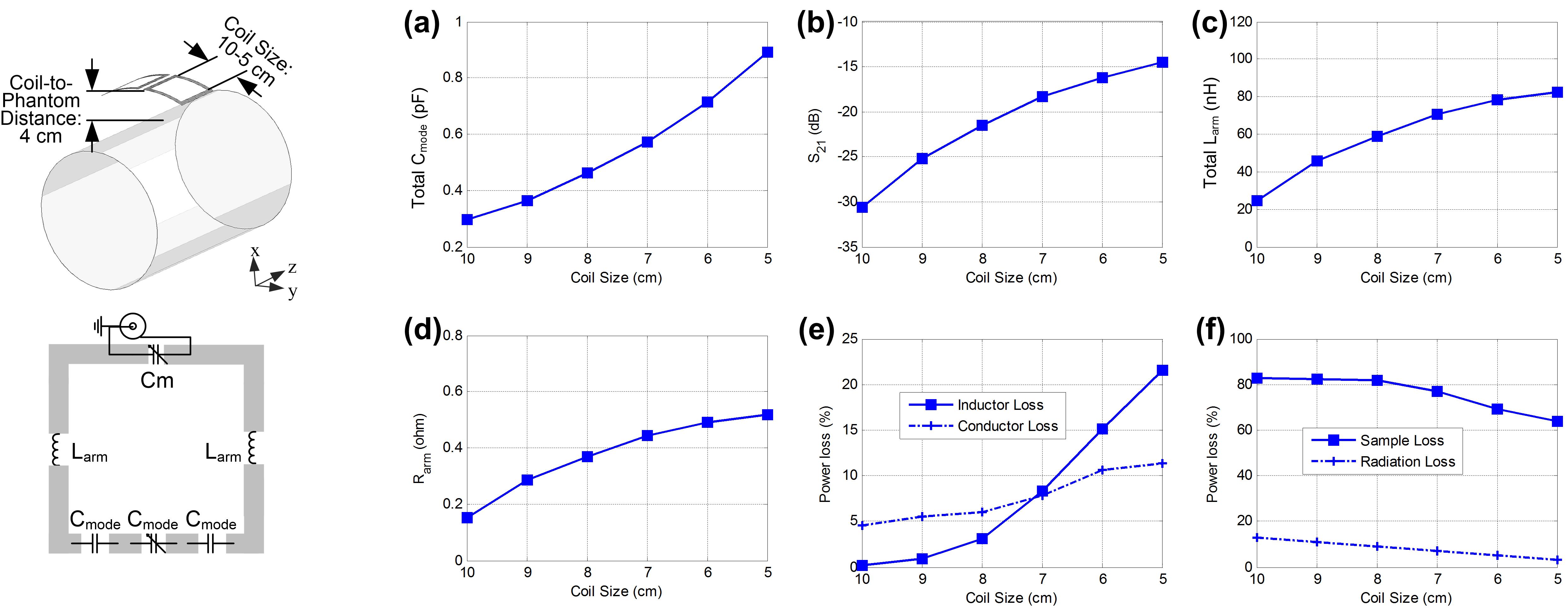
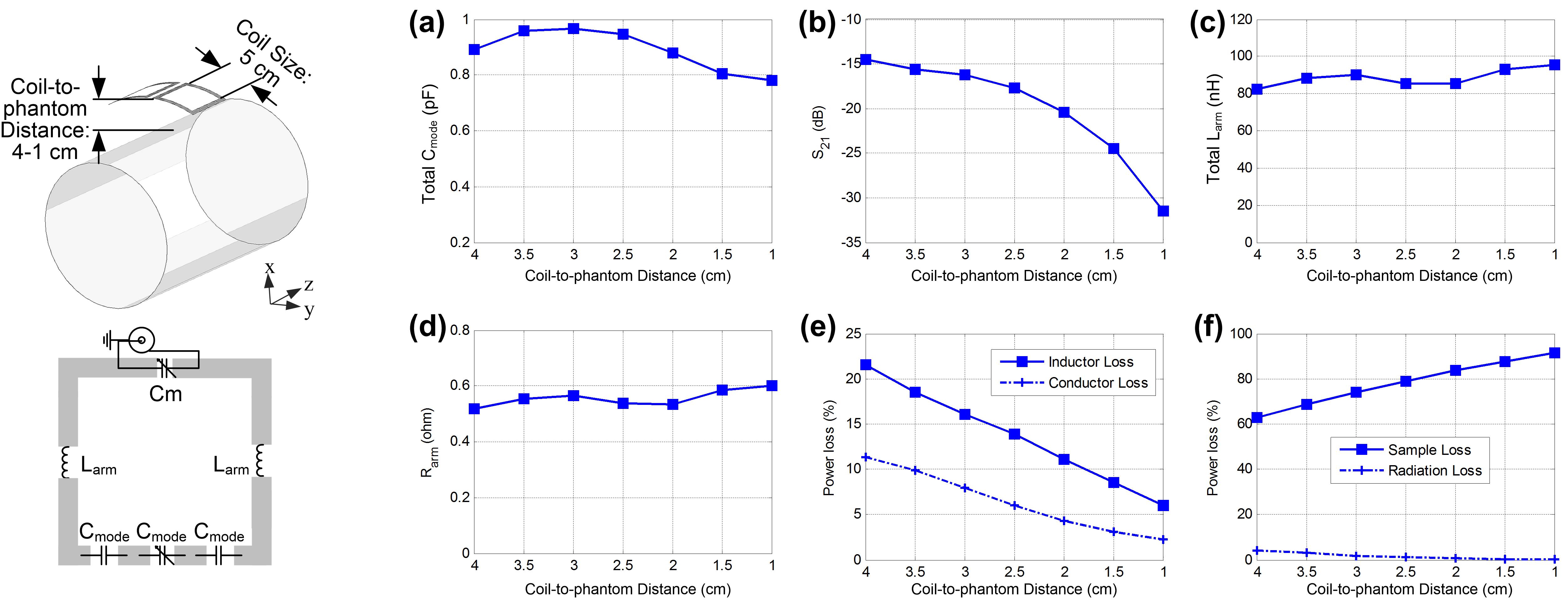
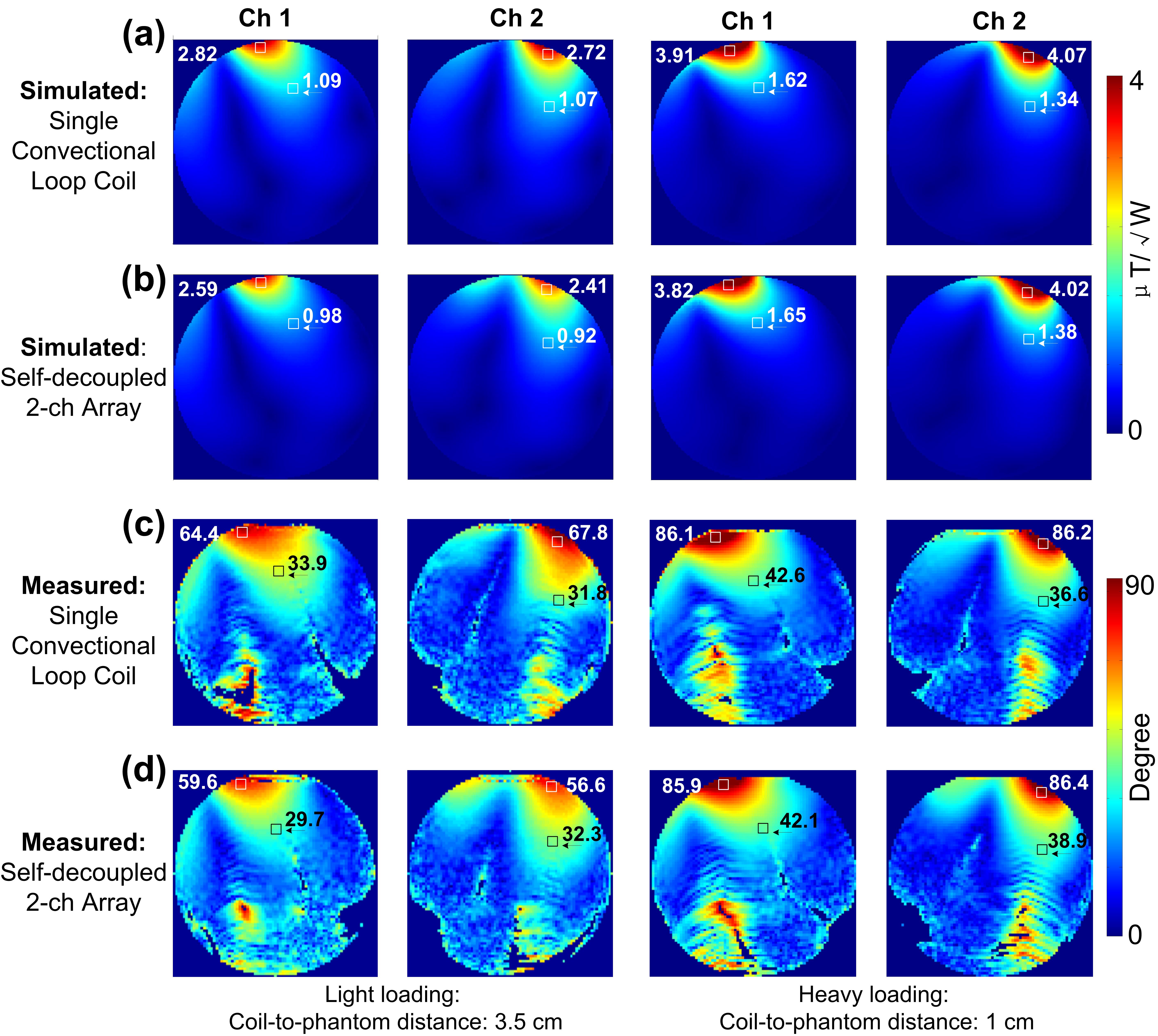
First, we numerically analyzed the power losses of self-decoupled coils for different coil dimensions (square loop, from 10x10 cm2 to 5x5 cm2) with light loading, as shown in Fig 1. Second, we analyzed a small self-decoupled coil (fixed-sized: 5x5 cm2) in various loading conditions (coil-to-phantom distance varying from 4 cm to 1 cm), as shown in Fig. 2. Third, we compared the transmit efficiency of the small self-decoupled coil through simulation and MR experiments. Finally, we built a 4-ch self-decoupled array and obtained GRE images of different samples to validate its performance. Simulations were performed using HFSS and Designer (ANSYS, Canonsburg, PA, USA). The input power in all simulations was 1 Watt. MR experiments were performed on a 7T whole-body scanner (Philips Healthcare, Best, Netherlands). All coil elements were measured individually, used in transmit/receive mode and driven with the same input power. Axial B1+ maps were acquired of a 15-cm diameter cylindrical phantom using the DREAM method9.Results
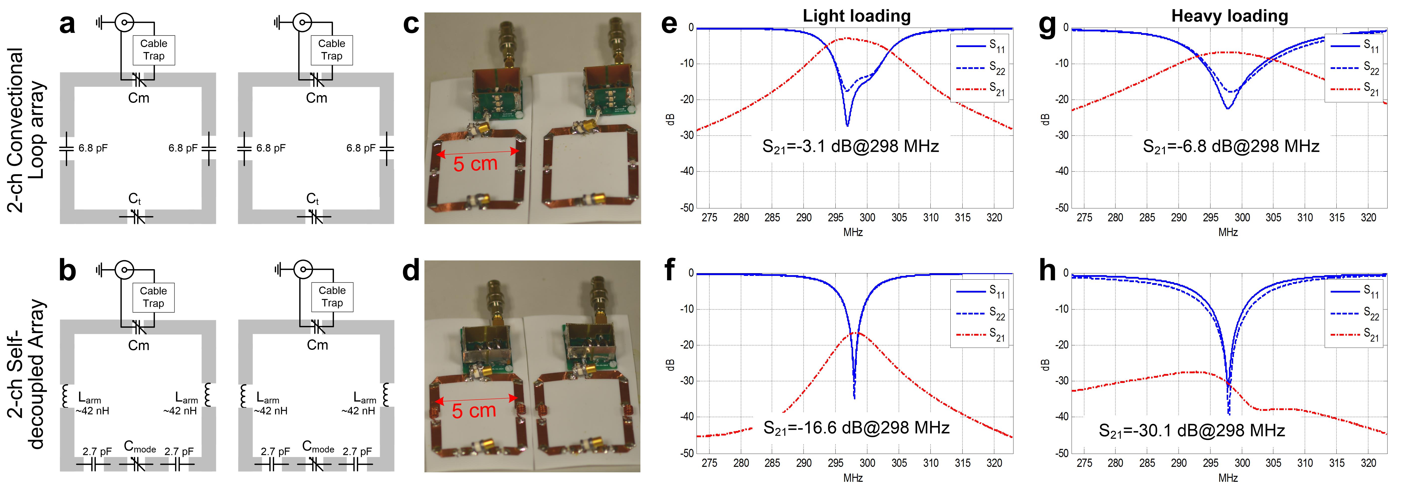
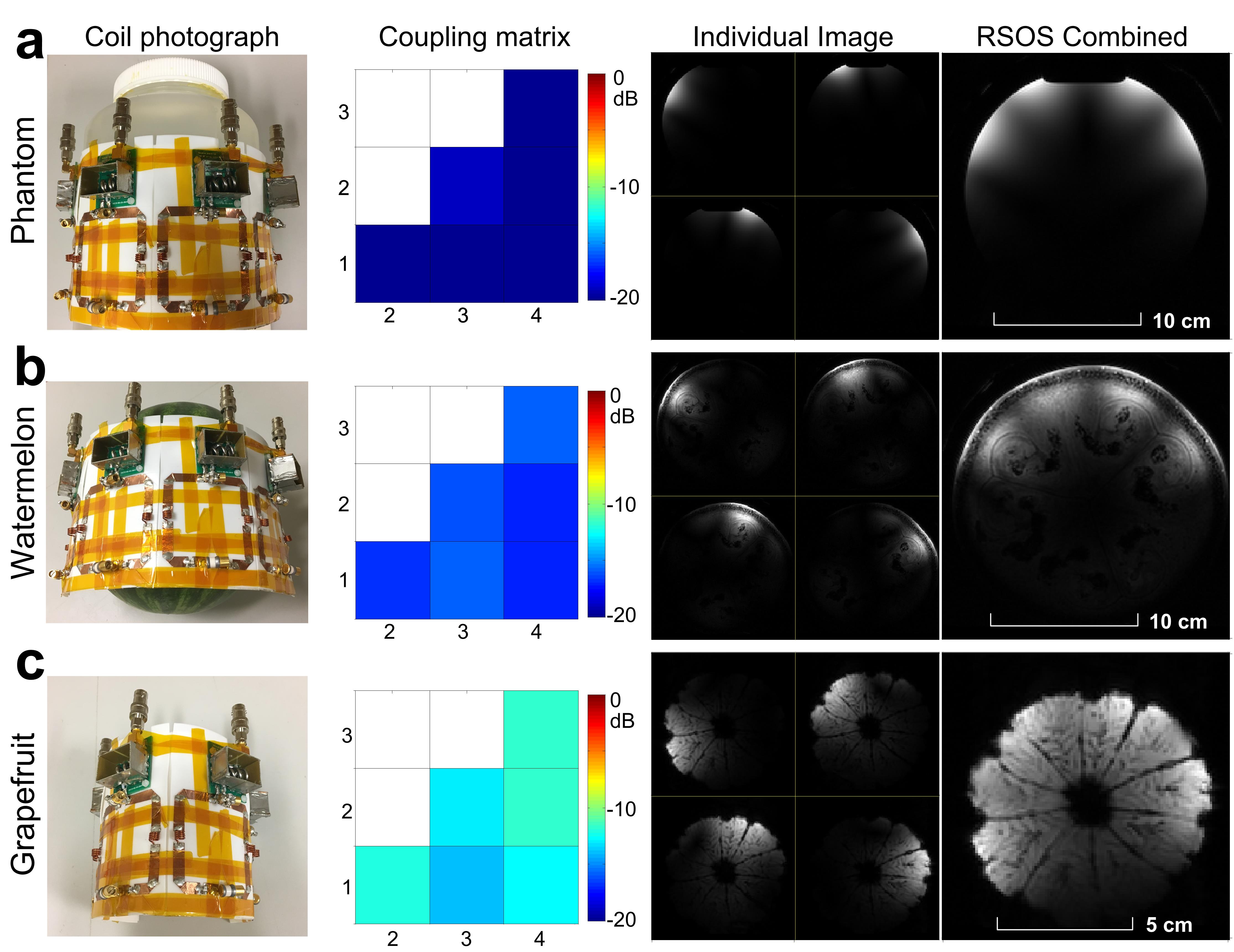
Figs. 3a-3d show schematics and photographs of a 2-ch conventional array and a 2-ch self-decoupled array. In the conventional coil, four capacitors were used to equally segment the conductor. For the self-decoupled coil, three mode capacitors (Cmode) were used to balance the dipole and loop mode coupling, and inductors (Larm) were added to tune the resonant frequency back to 298 MHz. Without decoupling, the conventional coils were strongly coupled to each other (Figs. 3e and 3g), which was especially severe with light loading (-3.1 dB, i.e., 49% power cross-talk). For self-decoupled coils, however, the coupling was only -16.6 dB (2.2% power cross-talk) for light loading and -30.1 dB (0.1% power cross-talk) for heavy loading (Figs. 3e and 3g). Figs. 4a and 4b show simulated B1+ maps for an ideal single conventional coil (without the presence of the other coil) and from one coil of the self-decoupled array (with the other coil terminated with 50 ohms), respectively. In the light loading case, the transmit efficiency of the self-decoupled coil is about 10% lower than the ideal conventional coil, which can be attributed to the power loss in Larm. In the heavy loading case, the transmit efficiency of self-decoupled coils is almost the same as that of the ideal conventional coil. These results are consistent with the power analysis in Fig. 2. The B1+ simulation results were validated in MR experiments, as shown in Figs. 4c and 4d. Fig. 5 shows bench test results and MR images on different samples (a-b-c: phantom-watermelon-grapefruit) using the 4-ch small self-decoupled array.Discussion and Conclusion
The mode capacitance Cmode increased as the coil size decreased, which mitigated the amount by which the inductance Larm had to increase. It was found that the performance of self-decoupled arrays could be well preserved so long as the sample loss dominates. Due to the loss from Larm, the small self-decoupled coil (5x5 cm2) had a 10% transmit efficiency decrease in the light loading case, compared to an ideal conventional coil. This is a small tradeoff considering its simple structure and excellent decoupling performance. We note that the power loss is within the coil circuit and does not affect the safety efficiency (B1+/√SAR). With heavy loading (e.g., coil-to-phantom 1 cm), no transmit efficiency decrease was observed even for the 5x5 cm2 sized coil. The observed decoupling performance proved robust across loading conditions. Based on these simulation and experimental results, the self-decoupled coil appears to be a good candidate for dense coil arrays at ultrahigh fields.Acknowledgements
This work is supported by NIH Grants R01 EB016695 and R21 EB 018521.References
1. Roemer, P.B., Edelstein, W.A., Hayes, C.E., Souza, S.P. & Mueller, O.M. The NMR phased array. Magn Reson Med 16, 192-225 (1990).
2. Sodickson, D.K. & Manning, W.J. Simultaneous acquisition of spatial harmonics (SMASH): fast imaging with radiofrequency coil arrays. Magn Reson Med 38, 591-603 (1997).
3. Pruessmann, K.P., Weiger, M., Scheidegger, M.B. & Boesiger, P. SENSE: sensitivity encoding for fast MRI. Magn Reson Med 42, 952-62 (1999).
4. de Zwart, J.A., Ledden, P.J., Kellman, P., van Gelderen, P. & Duyn, J.H. Design of a SENSE-optimized high-sensitivity MRI receive coil for brain imaging. Magn Reson Med 47, 1218-27 (2002).
5. Griswold, M.A. et al. Generalized autocalibrating partially parallel acquisitions (GRAPPA). Magn Reson Med 47, 1202-10 (2002).
6. Snyder, C.J. et al. Comparison between eight- and sixteen-channel TEM transceive arrays for body imaging at 7 T. Magn Reson Med 67, 954-64 (2012)
7. Erturk, M.A., Raaijmakers, A.J., Adriany, G., Ugurbil, K. & Metzger, G.J. A 16-channel combined loop-dipole transceiver array for 7 Tesla body MRI. Magn Reson Med 77, 884-894 (2017).
8. Yan X, Gore J C, Grissom W A, Self-Decoupled RF Coils, ISMRM, p. 757 (2017).
9. Nehrke, K. & Bornert, P. DREAM--a novel approach for robust, ultrafast, multislice B(1) mapping. Magn Reson Med 68, 1517-26 (2012).
Figures