1701
Magnetically coupled RF coil for optimizing noise correlation1Research & Development Group, Hitachi, Ltd., Tokyo, Japan, 2Healthcare Business Unit, Hitachi, Ltd., Tokyo, Japan
Synopsis
A magnetically coupled radiofrequency (RF) coil (MC coil) for optimizing noise correlation has been developed. The electric fields of each RF coil, which determine noise correlation, were controlled by a small magnetic coupling between a pair of RF coils. The MC coil was implemented as a two-channel loop coil in 1.5 T magnetic resonance imaging (MRI). The experimental results show that noise correlation can be controlled by using a small magnetic coupling without signal-to-noise ratio (SNR) loss. MC coils that can optimize noise correlation give a new degree of freedom to coil design.
Introduction
Noise correlation (NC) is a very important factor regarding obtaining high SNR images reconstructed from multichannel RF coils1,2. The NC coefficient is given by the coupling between the electric fields (E-fields) that are generated by each pair of coils. It is an important indicator of coil quality not only for magnetic coupling but also for robust performance. However, to obtain high sensitivity, magnetic decoupling to avoid a split in the frequency of resonance due to magnetic coupling has priority, and for that reason, elimination of the E-field coupling has not been optimized. Therefore, NC remains high, and errors in the noise measurement may affect the SNR of the images. To alleviate this problem, we have developed magnetically coupled RF coil (MC coil) for optimizing NC, and in this paper, we demonstrated that they can eliminate the NC.Materials and Methods
Coil design:
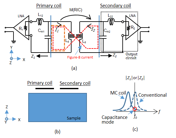
MC coil was designed for optimizing the NC coefficient between a pair of coils by using a small magnetic coupling between the same pair. Figure 1 (a) is a diagram of the 2ch MC coil, which has an inductive decouple circuit (Ld) to adjust the coupling. Individual coils were placed to be line-symmetrically when viewed from the sample (Fig. 1 (b)). The resonance frequency of the secondary output circuit was adjusted to be about 10–15% lower than the magnetic resonance frequency (f0) using Cm1 and Cm2 (Fig. 1 (c)). This caused resonant inductive coupling (RIC) between the primary and secondary coils, and a coupling current (I2) occurred in the secondary coil, whose phase was shifted by 180 degrees. This coupling current together with the current of the primary coil created a figure-8 current. When viewed from the secondary coil, the primary coil operated similarly. The NC ($$$k_{ij}$$$) is calculated as the following integral in the volume ($$$V$$$) of a sample1
$$k_{ij}=\frac{R_{ij}}{\sqrt{R_{ii}R_{jj}}}$$
$$R_{ij}=\sigma\int_{V}^{}E_{i}\left(x,y,z \right)\cdot E_{j}^{*}\left(x,y,z \right)dV$$
where $$$\sigma$$$ is the conductivity of the sample, and $$$E_{i}\left(x,y,z \right)$$$ and $$$E_{j}\left(x,y,z \right)$$$ are the E-fields generated by coils i and j, respectively. In the case of conventional coils that are next to each other, $$$k_{ij}$$$ is positive because the two coils generate similar E-fields in most areas. On the other hand, in the MC coils, $$$k_{ij}$$$ is reduced by the figure-8 current because it generates a negative inner product around the secondary coil.
Simulations:
We numerically calculated the E-fields and sensitivity of the coils using an in-house simulator based on method of moments 3. A 2ch 100 mm square loop array was constructed with coil gaps of 100, 140, and 200 mm. The coils were tuned/matched to 64 MHz.
Experiments:
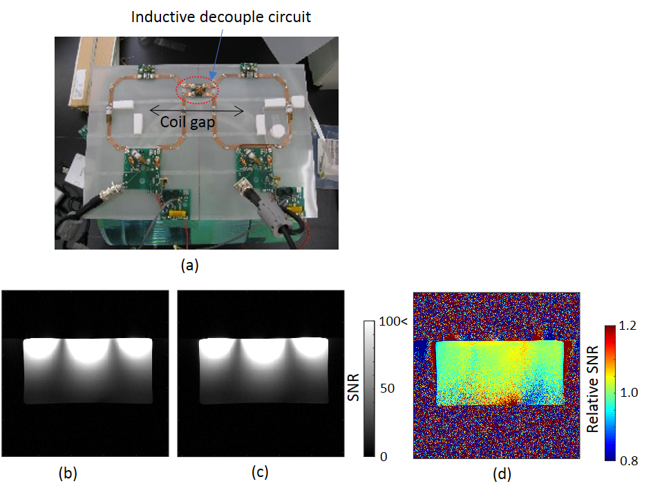
The 2ch loop array was constructed with coil gaps of 140 mm and tested for two coupling (current ratio) cases: a conventional coil (<2%), and an MC coil (about 10%). The coils were placed on a plane vertical to a static magnetic field to evaluate them on the different magnetic field (B1) orientations. Phantom images were obtained on a 1.5 T MRI (Spin-echo, TR/TE = 500/30 ms, thickness = 2 mm, FOV = 450 mm, and matrix size = 256 × 256). Noise-only data were acquired without RF pulses and the NC matrix was obtained1. A rectangular phantom (350 x 180 x 270 mm3, 10 mM NiCl2, and 0.4 wt% NaCl solution) was used. The SNR was calculated by $$$SNR=\sqrt{\bf S^{H} R^{-1} S}$$$, where $$$\bf S$$$ is a vector of each coil signal at the same pixel and $$$\bf R$$$ is the NC matrix (whose elements are the coefficients $$$R_{ij}$$$).
Results and Discussion
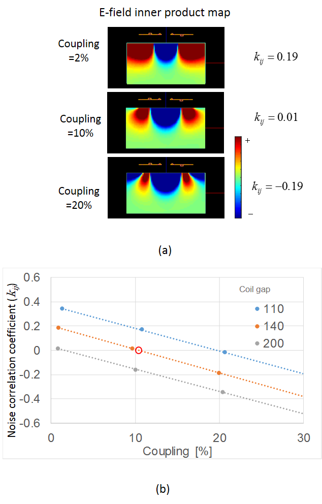
Figure 2 (a) shows numerically simulated inner product maps of E-fields when the coupling strength was changed. These images show that the dominant area changed from plus to minus depending on the strength of the coupling. The relationship between NC and coupling strength for each coil gap was calculated and plotted (Fig. 2 (b)). The NC was reduced by the strength of the coupling. In the case of 140 mm, the NC became zero at about 11% coupling. Figure 3 (a) shows the constructed coil. SNR images of two cases of coupling were obtained (Figs. 3 (b) and (c)). The NC coefficients were −0.15 and 0.01, respectively. Figure 3 (d) shows the map of the relative SNRs of the MC coil to the conventional coil. These results indicate that the SNR did not decrease by RIC and that the NC was controlled.Conclusion
We have developed an MC coil. Using a 2ch MC coil, we have demonstrated that NC can be controlled without SNR loss. MC coils that can optimize NC give a new degree of freedom to coil design.Acknowledgements
No acknowledgement found.References
1. Roemer PB, Edelstein WA, Hayes CE, et al. The NMR phased array. Magn Reson Med. 1990 Nov;16(2):192-225.
2. Pruessmann KP. Encoding and reconstruction in parallel MRI. NMR Biomed. 2006 May;19(3):288-99.
3. Ochi H, Yamamoto E, Sawaya K, Adachi S. Calculation of electromagnetic field of an MRI antenna loaded by a body. Proceedings of the 11th Annual Meeting of SMRM, Berlin; 1992. p 4021.
Figures