1699
A Fast MOSFET RF Switch for TRASE MRI at Low Magnetic Field1Laboratoire Kastler Brossel, ENS-PSL Research University, CNRS, UPMC-Sorbonne Université, Collège de France, Paris, France, 2Rady Faculty of Health Sciences, College of Medicine, University of Manitoba, Winnipeg, MB, Canada, 3Department of Physics, University of Winnipeg, Winnipeg, MB, Canada
Synopsis
TRansmit Array Spatial Encoding (TRASE) MRI uses trains of B1 pulses alternatively produced by distinct transmit coils. Commonly used coil switching involving PIN diodes is too slow for low-field MRI and would introduce wait times between pulses typically as long as each individual pulse (hence, significant diffusion-induced resolution loss in TRASE MRI of gas samples). A MOSFET-based RF switch is described and characterised. Up to 200 kHz, it allows for sub-µs switching of RF currents from a single amplifier to several coils with sufficient isolation ratio and no delay between pulses.
Introduction
TRansmit Array Spatial Encoding (TRASE) is a MRI method using repeated pulses of radiofrequency (RF) B1 fields from different phase-gradient transmit coils instead of the standard imaging gradients of B0 to manage spatial encoding.1,2 An evaluation of the benefits and limitations of TRASE MRI at low field (a few mT) is under way using hyperpolarised gas samples.3,4 Fast switching between two or more transmit coils with sufficient isolation and negligible wait time between pulses is required to jointly reduce the total RF encoding time and the RF peak power. PIN diodes are often used for coil switching,2 but bias control with RF isolation involves response times (several RF periods) which are too slow for the targeted low-frequency application.Methods
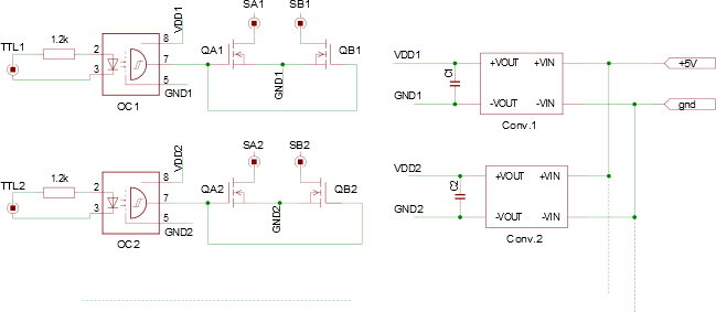
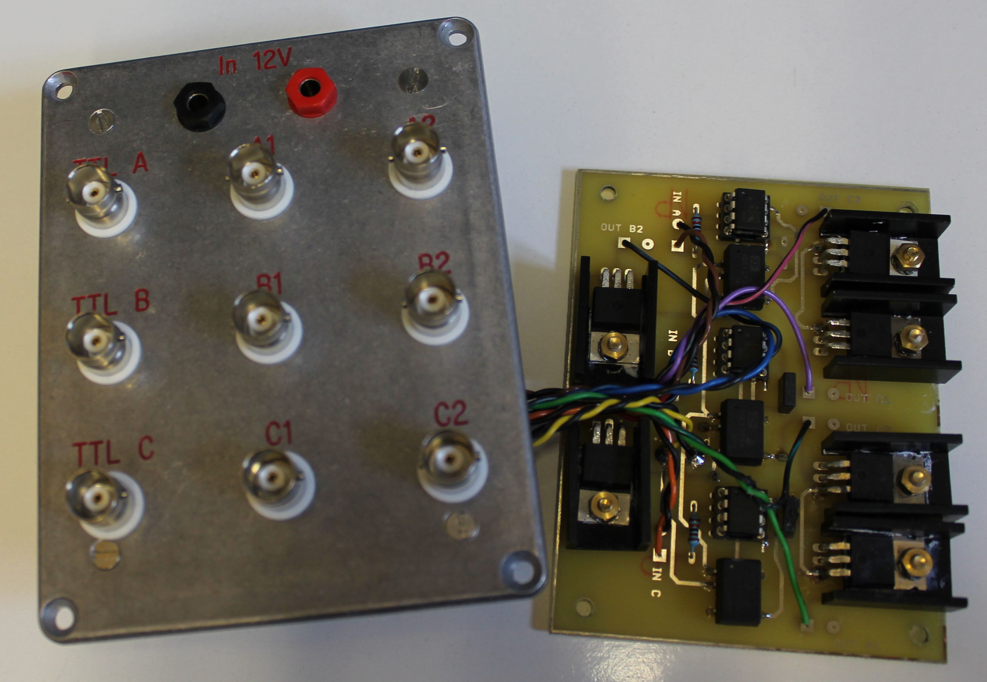
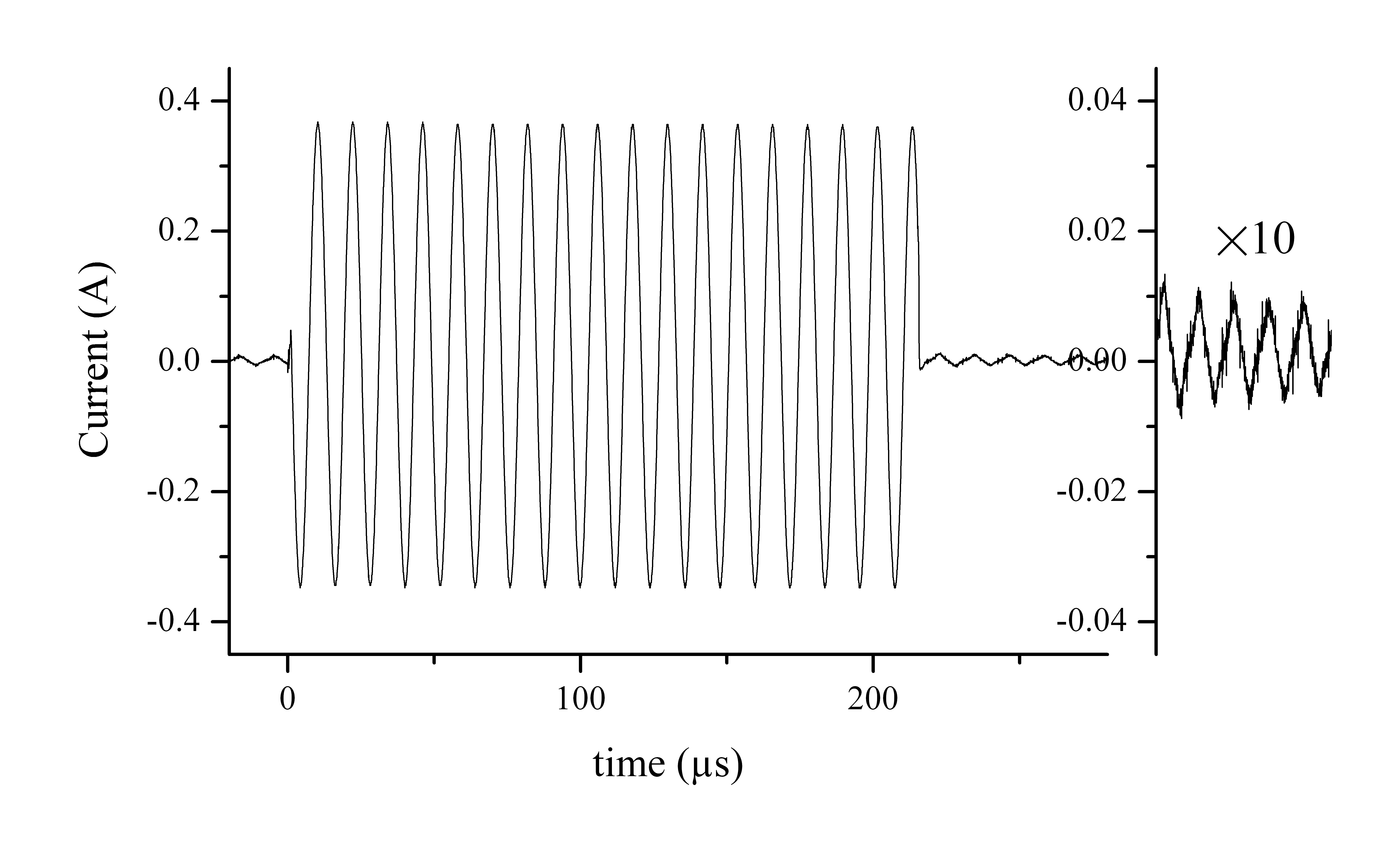
Switching times (delays and jitter) have been inferred from datasheet or measured for different mechanical switches (MEMS, Reed or standard relays). Bidirectional MOSFET switch prototypes, with floating and optically isolated gate control, have been designed and wired (Figs. 1 and 2). Electrical tests have been performed using different RF power amplifiers (a 250-W-peak, BT00250-Alpha A model, Tomco Technologies, and a 100-W-CW in-house linear amplifier), different loads (a 50-Ω resistive load or tuned and untuned transmit coils), and different frequencies (in the range DC – 200 kHz). An Apollo Tecmag console (low-frequency LF1 model), allowing for 100 ns time resolution of sequence events, was used to manage RF pulses and TTL signals to control switches. RF currents were recorded using a 4-channels digital oscilloscope by monitoring the voltage drop across a 1-Ω resistor inserted on the ground return line at the output of the RF amplifier.Results
Switching times of mechanical relays range from 10 μs (for MR- compatible MEMS5) to several ms. Fast reed relays are widely available and economical, can be operated in the vicinity of low-field MR systems, and have close/release times of 0.15/0.1 ms for typical carry currents of 1 A, while miniature relays with 4-A carry currents have typical switching times of 1 ms. The MOSFET switch of Fig. 2 (with IRF 840, up to 32 A) has switching times below 1 μs. It has a low ON impedance (about 1 Ω) and a frequency-dependent OFF impedance, consistent with a 500 pF capacitance. This usually provides efficient RF current switching, both on a resistive load (Fig. 3) and on transmit coils (various situations have been evaluated and will be reported). A small RF interference due to the operation of DC-DC converters is sometimes observed, but a suitable choice of the component eliminates the problem (different components operate at different switching frequencies).Discussion and conclusion
Although magnetically actuated relays provide an excellent switching efficiency and can be operated in low-field MR systems, their slow response times, on the same order as the duration of individual B1 pulses in TRASE sequences (typically3 10-20 RF periods around 100 kHz), introduce significant wait times during encoding pulse trains. This may result in prohibitive diffusion-induced resolution loss in gas samples, and acceleration through the use of shorter RF pulses is impractical due to Bloch-Siegert shifts and to the influence of concomitant RF fields.6 MOSFET-based switches eliminate wait times and RF pulse currents can be switched to different transmit coils with sufficient isolation ratio and no delay between pulses. A choice of the MOSFET components can be made to achieve a suitable compromise between reducing the OFF-state capacitance and managing the required RF voltage and current.Acknowledgements
Support from CNRS and ENS for joint work is gratefully acknowledged (CP B.).References
1. Sharp J.C. et al., Magn Reson Med 63:151 (2010); NMR
Biomed, 26: 1602 (2013).
2. Deng Q. et al., Magn Reson Imaging 31:891 (2013).
3. Nacher P.-J. et al., Proc ESMRMB15, Magn.
Reson. Mater. Phy. 28
Suppl. 1 (2015) p. S64.
4. Kumaragamage S. et al., Proc ESMRMB16, Magn.
Reson. Mater. Phy. 29 Suppl. 1
(2015) p. S34.
5. Spence D. and Aimi M., Proc Intl Soc Mag Reson Med. (2015) 23:704.
6. Bidinosti C.P. et al, this conference.
Figures