1698
A Neck Adapted 4-Ch Saddle-Shaped pTx Transceive Coil for Carotid Imaging at 7T1Medical Physics in Radiology, German Cancer Research Center (DKFZ), Heidelberg, Germany, 2Faculty of Electrical Engineering and Information Technology, FH Aachen - University of Applied Sciences, Aachen, Germany, 3Erwin L. Hahn Institute for MRI, University Duisburg-Essen, Essen, Germany, 4Center for Magnetic Resonance Research, University of Minnesota Medical School, Minneapolis, MN, United States, 5Medical Physics and Metrological Information Technology, Physikalisch-Technische Bundesanstalt (PTB), Berlin, Germany
Synopsis
Stroke is one of the most common causes of death, often caused by accumulation of plaques in the carotid arteries. This motivates investigating the anatomy and blood hemodynamics in the carotid bifurcation with high resolution. For early diagnostics, this work presents a new, saddle-shaped neck-adapted 4-channel parallel transceive coil for imaging at 7T. Coil design and optimization were performed using numerical simulations, and a safety assessment was performed with an anatomical body model. A head-shoulder phantom was built and used to validate measurements. High-resolution anatomical images and flow measurements were acquired in the common carotid artery.
Introduction
Ischemic stroke is often caused by narrowing of arteries in the head and neck. The origin of the embolus is, in many cases, the carotid bifurcation1,2. Accurate characterization of plaque in the bifurcation, using high field MRI, may help to identify high-risk patients preventively3. Several coils for carotid imaging at 7T have been presented previously4, 5, 6. In this work, a single-sided 4-channel transmit/receive carotid array was developed and evaluated. The coil has a similar layout to a previously presented double-sided 8-channel transmit/receive carotid coil array4; however, our coil has several major differences: it is saddle-shaped, uses non-overlapping loops, and is directly fixed to the subject’s neck using straps. The shape allows tight fitting to the neck to increase the transmit efficiency and, in combination with the straps, achieves a comfortable setup for the patients. The coil offers B1+ shimming capabilities for subject- and region-specific optimization of the flip angle. Its use was demonstrated for 2D gradient echo imaging and 4D flow MRI7.Methods
Coil development and field simulations:
A tight-fitting saddle-shaped coil carrier was built by bending 2.0mm thermoplastic sheet (Efficast, Orfit Industries, Antwerp, Belgium) around the neck of a realistic head-and-shoulders-shaped phantom. The coil array consists of four loops, whose projections are square shaped with an outside edge length of 35mm if seen from a sagittal view. They are made from 2mm-wide copper tape bent onto the carrier.
Loops were arranged in a 2×2 grid with 0.5mm spacing between them (Fig. 1). Bending the loops onto the former allowed for tight fitting to the neck.Loops were decoupled using inductive decoupling networks. Each loop was connected to an external T/R switch and preamplifier (not shown).
Electromagnetic simulations were performed (CST Studio Suite 2016, Computer Simulation Technology Ag, Darmstadt, Germany) with the array loaded with the homogeneous head phantom and the Duke body model8. Tuning, matching, and decoupling were optimized in each case, and B1+ and 10g-SAR maps extracted. In the simulations, channels 2&3 (Fig. 1) were driven with a phase of 90° with respect to channels 1&4.
Scanner measurements:
MR measurements were performed on a 7T whole-body MRI system (Magnetom 7T, Siemens, Erlangen, Germany) in pTx mode. Phantom measurements were made using a 3D-printed head-and-shoulders phantom (Fig.1) filled with a tissue-simulating liquid based on water, Polyvinylpyrrolidone (PVP), and sodium chloride (εr=40.22, σ=0.515 S/m at 297MHz).
The coil was first tuned, matched, and decoupled using a network analyzer (Agilent E5071, Agilent Technologies, CA, USA) while loaded with the head-and-shoulders phantom. B1+ maps were then acquired using a vendor-provided multi-slice TurboFLASH sequence, and the transmit efficiency B1+/√Pin was calculated. Simulated B1+ maps were spatially matched to measured maps and divided pixel-wise. The mean efficiency ratio was then determined in two ROIs.
Tuning, matching, and decoupling were then repeated in two healthy volunteers. A multi-slice 2D GRE (TR/TE=9.1/5.2ms, 0.4x0.4x3mm3, FOV=150x200) and a 4D flow sequence (TR/TE=37.8/3.465ms, 1x1x5mm3, FOV=192x192) were then acquired, and time-resolved mean flow velocities were obtained over a cross-section of the common carotid artery (CCA).
Results
Simulated and measured S-parameters for the phantom are summarized in Table 1. A maximum coupling of -11.2 and -11.6dB was found for the diagonally located elements (1&3 and 2&4, Fig. 1).
Mean B1+ ratios (simulated/measured), used to validate the simulation results, were 1.23±0.36. Simulations with the anatomical model resulted in a SAR10g,max of 3.5W/kg (Pin = 1W) as shown in Fig. 2. To comply with local SAR limits9 for the normal (first-level) mode of 10W/kg (20W/kg), the maximum total time-averaged input power should be limited to 2.9W (5.9W). Including a safety margin based on the deviation between the measured and simulated B1+, the maximum amplitude was set to 2W (0.5W/channel). A mean transmit efficiency B1+/√Pin of 1.35µT/√W (0.89 µT/√W) was determined close to the carotid bifurcation after (before) phase shimming (Fig. 3). Successful identification of the carotid bifurcation with good contrast could be achieved as shown in Fig. 4. Furthermore, flow velocity quantification resulted in a comparable pattern in the CCA to that presented before10.
Discussion and Conclusion
In this work, a new 4-channel parallel transceive coil for imaging of the carotid arteries was presented. The optimized shape allows a tight and comfortable fit to the subjects’ neck. High-resolution anatomical images were obtained as well as flow quantification in the common carotid artery and the internal jugular vein. A potential application of this coil is flow MRF11 to simultaneously quantify relaxation parameters and blood velocities in the bifurcation at 7T.
Acknowledgements
No acknowledgement found.References
1. Schünke, M; et al. Kopf, Hals und Neuroanatomie. Prometheus LernAtlas der Anatomie. Thieme. 2009
2. The Internet Stroke Center. Ischemic Stroke. http://www.strokecenter.org/patients/about-stroke/ischemic-stroke/. Accessed October 10. 2017
3. Virmani, R; et al. Pathology of the thin-cap fibroatheroma: a type of vulnerable plaque. Jurn. Interv Cardiol. Jun 2003;16(3):267-272.
4. Adriany, G; et al. A 16-channel Arterial Spin Labeling – Head Transceiver Array Combination for 7 Tesla. Proc. Intrl. Soc. Magn. Reson. Med. 22:0317. 2014
5. Kraff, O; et al. An Eight-Channel Transmit/Receive RF Array for Imaging the Carotid Arteries at 7 Tesla. Proc. Intl. Soc. Mag. Reson. Med. 17. 2009
6. Kraff, O; et al. A Transmit/Receive Radiofrequency Array for Imaging the Carotid Arteries at 7 Tesla. Investigative Radiology 46(4):246-254. 2011
7. Markl, M; et al. 4D flow MRI. Mag. Res. Im. 36(5):1015-1036. 2012
8. Christ, A; et al. The Virtual Family–development of surface-based anatomical models of two adults and two children for dosimetric simulations. Phys med biol. 2010; 55(2):N23–N38
9. International Electrotechnical Commission (IEC), 2015. IEC 60601-2-33 Medical electrical equipment - Part 2-33: Particular requirements for the basic safety and essential performance, Edition 3.2. ISBN 978-2-8322-2743-5.
10. Schmitter, S; et al. Simultaneous MultiSlab 4D Flow MRI for Quantification Hemodynamics in the Carotid Bifurcation at 7 Tesla. Proc. ISMRM 2017:1257
11. Flassbeck, S; et al. Quantification of Flow Magnetic Resonance Fingerprinting. Proc. ISMRM 2017:0128
12. Avdievich, N I; et al. Resonant inductive decoupling (RID) for transceiver arrays to compensate for both reactive and resistive components of the mutual impedance. NMR in Biomedicine. 2013; 26: 1547-1554
Figures
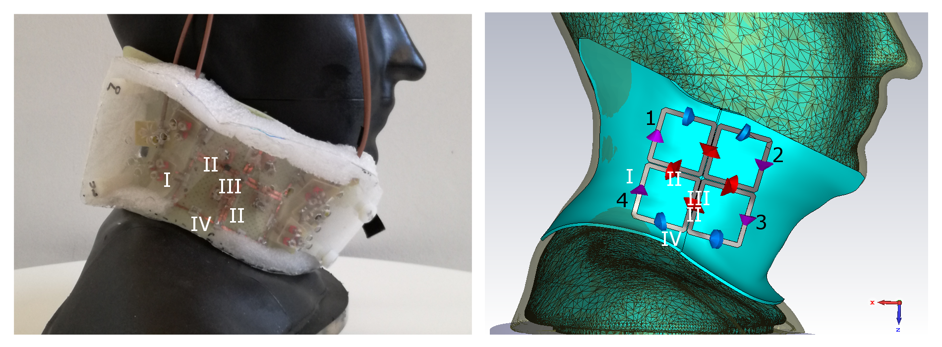
Figure 1: Left: Experimental set-up of the 4-channel carotid coil including a homogeneous phantom. Right: Simulation model with the phantom. Coil numbering is indicated in black numbers 1-4. The following components were used in all channels analogously:
I (purple): Entry supplies, including cable traps and matching and tuning networks, II (red): Decoupling loops with an inductance of approximately 10nH, III (not visible): Passive cross talk circuits12 (consisting out of a loop (L ≈ 20nH) and an adjustable capacitance (10.2 to 15.0pF)) between two neighbouring decoupling loop, IV (blue): Segmentation via chip capacitors (C=4.3pF).
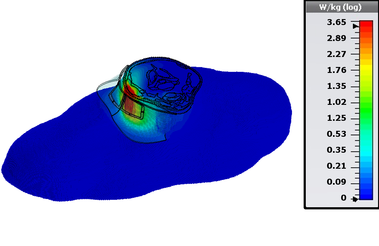
Figure 2: Local SAR distribution in the neck of the Duke body model for a total input power of 1W (0.25W/channel). Channels 2&3 (Fig. 1) were driven with a phase of 90° compared to channels 1&4.


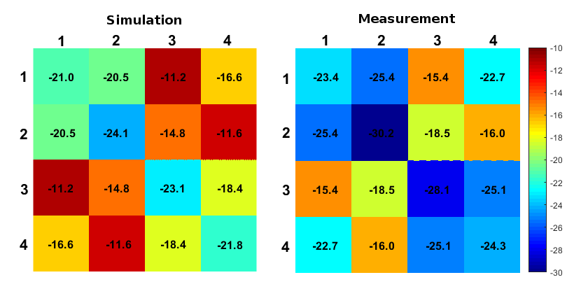
Table 1: Comparison between (left) simulated and (right) measured S-parameters, shown in dB. Measurements were performed on the workbench with a network analyzer. S-matrices in simulation and measurement were optimized separately.