1696
A meander slot element with microstrip line match and tune1Texas A&M University, College station, TX, United States
Synopsis
lot antennas have been widely used in communications because of their obvious low-profile nature. In MRI applications, the ability to ‘hide’ ancillary electronic components behind a shield containing a slot antenna could lead to interesting and very “clean” transmit antenna designs. Using the meander slot as elements for multi-channel coils allows for more compact multi-channel transmit coil designs with a shielded “clean” imaging area. This shielded imaging area provides a desirable environment for placing a receiver coil. More importantly, using meander slot coil elements can potentially allow for the design of multi-channel coils without the need of using matching and tuning networks or decoupling circuits. We believe this may significantly simplify the design of multi-channel transmit coils.
Introduction
Slot antennas have been widely used in communications because of their obvious low-profile nature. In MRI applications, the ability to ‘hide’ ancillary electronic components behind a shield containing a slot antenna could lead to interesting and very “clean” transmit antenna designs. Additionally, slot antennas may exhibit low coupling, potentially enabling array designs that do not need any decoupling methods. We have previously reported an eight channel, sixteen element volume coil using bowtie slot elements [1]. While the slots elements did not require any decoupling circuitry, they did use conventional lumped element match and tune networks to match to 50 ohms. Here we report a variation on the slot element, the meander slot, which uses a spiral extension section to enable a higher slot impedance. The higher impedance allows the slot to be easily matched using conventional microstrip line techniques, avoiding the use of lumped elements. The performance of the meander slot element is compared to the bowtie element. The meander line element performs essentially equivalently to the bowtie, but can be fabricated with only printed circuit techniques and requires no lumped elements. We believe this new element may be very useful for array design both because of the extreme low-cost of fabrication and because of the advantageous coupling properties.Methods
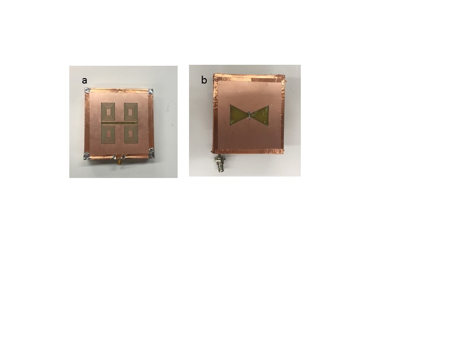
Slot antennas have been used widely in the telecommunication systems, however, have recently begun start to be investigated as MRI coils. Here we report a meandered slot element. The meander slot coil geometry presented here is based on a miniaturized slot antenna presented by [2]. The radiating slot length is 55 mm with four spirals meander ending, this structure was LPFK on a 10 cm×10 cm wide single sided PCB (see Fig 1.a.). The feeding structure is a microstrip feed line extended from the back of the PCB on the FR4 layer across and below the center of the slot, etched on the other side of the PCB. Using a 55 mm bow-tie slot element with similar ground plane dimensions allowed for evaluating the performance of the meander slot coil. Coupling between coil elements represents one of the most challenging factors when designing multi-channel MRI coils. To evaluate coupling between the bowtie and meander slots, two of each element design were constructed . All four elements were matched and tuned to 50 Ω in the absence from other elements. Next each pair was placed in contact to measure the coupling level between elements. To evaluate relative B1 efficiency, a single element of each design was used as a transmit receive element in an imaging experiment. Images were acquired using the following acquisition parameters; gradient echo pulse sequence with 256×256 resolution, TR 1000 ms, TE 7 ms, 1 avg, slice thickness 2 mm, 100 KHz spectral width, 2.56 ms acquisition time and 28 dB receiver gain.Results
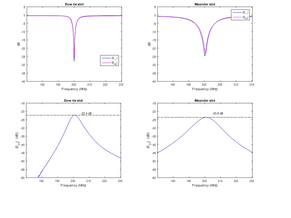
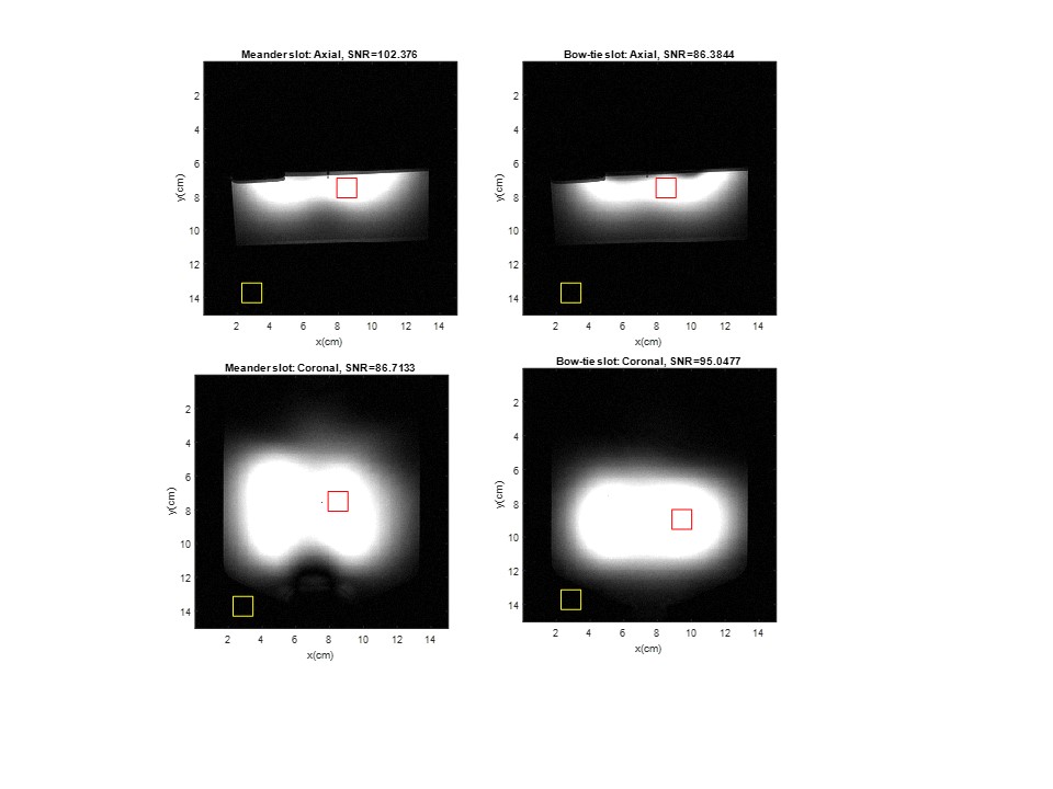
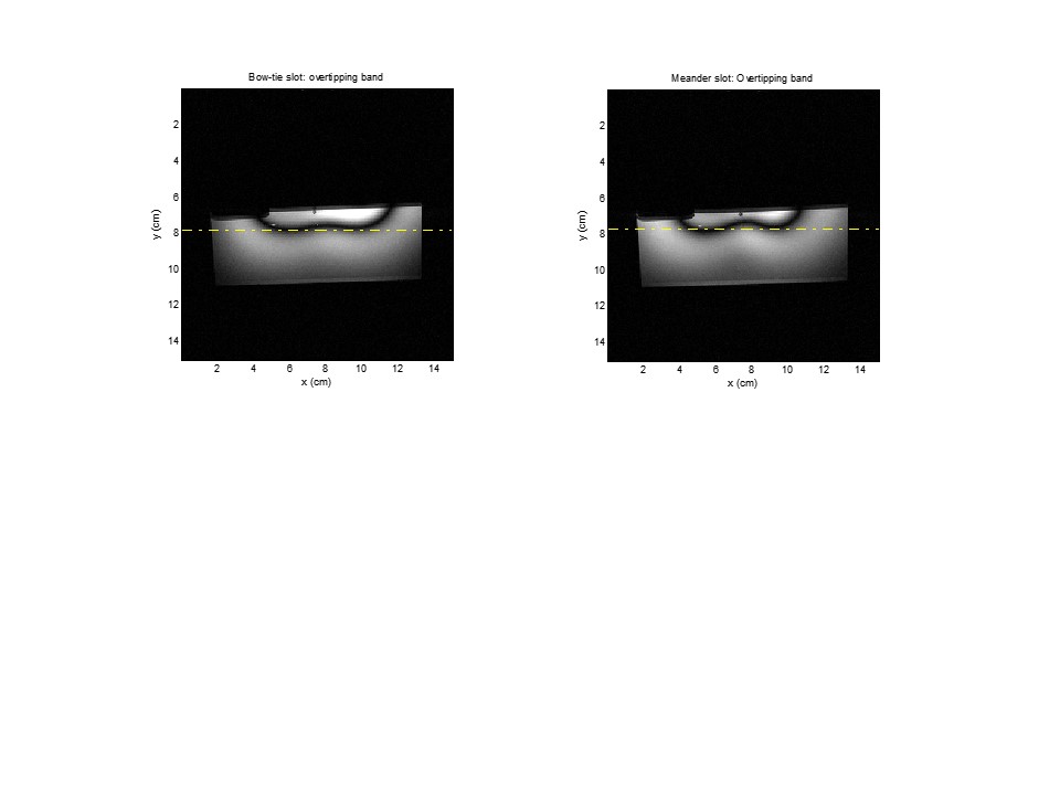
The acquired S21 data confirms the low coupling level between the meander slot elements. Without the addition of decoupling networks or preamplifier, the coupling was -23.6 dB and -22.3 for the meander slots and bow tie slots respectively (see figure 2). The imaging results, shown in Figure 3, demonstrate a symmetrical pattern for the meander slot and similar to the pattern exhibited by the bow-tie slot. This similarity eliminates the concerns of the radiation from the meander structure, and indicates that 55 mm slots vertical segment is the radiating structure. As a simple comparison of transmit efficiency, Figure 4 compares the location of the 180 tip angle location (dark band) when the same RF power was applied to both coils. This band occurred at approximately the same location, 1 cm away from the coil surface, for both coils indicating a similar B1+ efficiency.Discussions
Using the meander slot as elements for multi-channel coils allows for more compact multi-channel transmit coil designs with a shielded “clean” imaging area. This shielded imaging area provides a desirable environment for placing a receiver coil. More importantly, using meander slot coil elements can potentially allow for the design of multi-channel coils without the need of using matching and tuning networks or decoupling circuits. We believe this may significantly simplify the design of multi-channel transmit coils.Acknowledgements
No acknowledgement found.References
[1]. . Dheyaa Alkandari , Steven M. Wright. A 16 Element Bow-Tie Slot Array Coil for Parallel Transmit MRI/MRS. ismrm 2017
[2] Reza Azadegan and Kamal Sarabandi. A Novel Approach for Miniaturizationof Slot Antennas. IEEE TRANSACTIONS ON ANTENNAS AND PROPAGATION,2003
Figures