1695
A Prototype Four-Channel Parallel Transmission System to Investigate MRI Safety at 3 T1Physical Sciences, Sunnybrook Research Institute, Toronto, ON, Canada, 2Baylis Medical, Missisauga, ON, Canada, 3Medical Biophysics, University of Toronto, Toronto, ON, Canada
Synopsis
Interest in parallel transmission (pTx) continues to grow with many research groups investigating methods to increase channel count and applications on commercial MRI systems. It can be challenging, however, to integrate pTx hardware onto existing systems without disrupting normal operation. The present work successfully interposes a four-channel pTx system on an existing 3 T Siemens Prisma system and performs validation to demonstrate: (1) four-channel radiofrequency (RF) shimming; and (2) reduced RF heating in an electrically conductive implant.
Introduction
Interest in parallel transmission (pTx) continues to grow with many research groups investigating methods to increase channel count and applications on commercial MRI systems. It can be challenging, however, to integrate pTx hardware onto existing systems without disrupting normal operation. The present work successfully interposes a four-channel pTx system on an existing 3 T Siemens Prisma system. PTx system validation was performed to demonstrate: (1) four-channel radiofrequency (RF) shimming; and (2) reduced RF heating in an electrically conductive implant.Methods
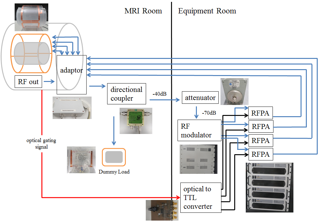
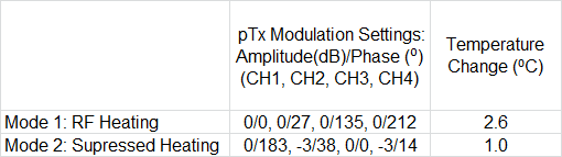
The four-channel prototype pTx system has a peak output power of 4 kW and integrates with the Siemens MRI system as shown in Fig 1. A custom four-channel adaptor module (Stark Contrast, Erlangen, GER) equipped with a Tim4G plug connects to the MRI system and provides access to the existing transmit/receive (TxRx) pathway. The adaptor module also has connections for a four-channel TxRx coil. The existing RF transmit signal (on the adaptor module) is connected to a 40 dB directional coupler (C11082-13, Werlatone, Patterson, NY); the existing RF signal power is dissipated through a load and the small-signal output is further attenuated by 30 dB (8322, Bird Electronics, Cleveland, OH) before being input into the RF modulator (CGP-128-4C, CPC, Hauppauge, NY). The RF modulator splits the input into four independent signals, with adjustable amplitude and phase via a web interface, that each connect to a separate 60 dB RF power amplifier (RFPA) (BT01000-AlphaSA, Tomco Technologies, Stepney, AUS) and feed back into the adaptor module for TxRx coil transmission. The RFPAs are blanked by converting the optical signal from the MRI system to an RFPA-compatible transistor-transistor logic signal. Prototype pTx system verification included an RF shim test and an RF heating test. For the RF shim test, the phases on the RF modulator were adjusted to maintain the optimal 90⁰ offset between neighbouring channels during fast low angle shot (FLASH) MRI of a uniform cylindrical phantom (TR/TE/FA=100 ms/5 ms/20⁰). An image was acquired with sub-optimal RF shim for comparison (50⁰ phase shift to Channel 1). For the RF heating test, an initial experiment was conducted to verify previous simulation studies that calculated optimal amplitude and phase settings to minimize heating in targeted regions of electrically conductive implants1,2. Turbo spin echo (TSE) scans (TR/TE/FA = 516 ms/6.7 ms/150⁰, 3m 45s scan time) were acquired of a head-shaped gel phantom with an inserted fibre-optic temperature sensor (Opsens Inc., Quebec City, QC) placed at the exposed tip of implanted insulted copper wire approximating a realistic lead trajectory for a deep brain stimulation device. Amplitude and phase adjustments were applied (based on simulation) to achieve pTx operation in two modes: (1) for localized heating; and (2) for suppressed heating (scientific and technical details are reported in another submission).Results
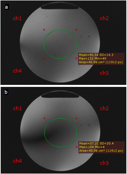
Fig. 2 shows images for (a) optimal and (b) sub-optimal RF shim settings. In the optimal condition, the mean and standard deviation of the MRI signal were 91 and 14, respectively, in the central region-of-interest (ROI, green outline). Image uniformity deteriorated with the sub-optimal RF shim such that the mean decreased by 36% and the standard deviation increased by 40% in the ROI. During the RF heating tests, imaging in mode 1 raised the temperature near the tip of the wire by 2.6⁰C (from 22.8⁰C to 25.4⁰C), whereas mode 2 produced only 1⁰C elevation (from 22.9⁰C to 23.9⁰C). Fig. 3 summarizes the RF heating test results and the pTx modulation settings (accounting for phase variation at the four-channel TxRx coil) to maintain 90⁰ between neighbouring channels for mode 1 and optimized amplitude and phase settings for mode 2.Discussion
The optimal RF shim image (Fig. 2a) agrees reasonably well with previous pTx results3,4. As expected, sub-optimal shim setting on channel 1 degraded signal strength and image uniformity. Furthermore, the pTx platform demonstrated a ~62% reduction in RF heating that is consistent with previous experimental results in the laboratory with different implant geometries2Conclusion and Future Work
A prototype four-channel pTx platform has been integrated successfully with a 3 T Siemens Prisma MRI system. The modular system design offers the flexibility and ease to increase channel count and replace hardware components. Future work will include more advanced experiments and hardware optimization.Acknowledgements
1. Canada Foundation for Innovation
2. Natural Sciences and Engineering Research Council of Canada
References
[1] McElcheran et al., “Parallel Transmission for Heating Reduction in Realistic Deep Brain Stimulation Lead Trajectories” ISMRM (2017)
[2] McElcheran et al., “Parallel Radiofrequency Transmission at 3 Tesla to Improve Safety in Bilateral Implanted Wires in a Heterogeneous Model” MRM (2017)
[3] Ullmann et al., “Experimental Analysis of Parallel Excitation Using Dedicated Coil Setups and Simultaneous RF Transmission on Multiple Channels”, MRM (2005)
[4] Stang et al., “An Extensible Transmit Array System using Vector Modulation and Measurement”, ISMRM (2008)
Figures