1517
Dedicated 1.5T 16 channel array for MR-guided radiation treatment planning of head and neck tumors1Department of Radiation Oncology, University of Würzburg, Würzburg, Germany, 2Rapid Biomedical GmbH, Rimpar, Germany, 3Department of Radiology, University of Würzburg, Würzburg, Germany
Synopsis
Precise target delineation and safety margin definitions are mandatory in radiation treatment of head and neck tumors. In this context, magnetic resonance imaging (MRI) is increasingly used in addition to computed tomography (CT) in the treatment planning system because of its superior soft tissue contrast. In this work, a novel 16 channel head and neck array coil is presented, which is adapted to the special requirements of radiotherapy planning. It allows for MR imaging of patients with brain and head and neck tumors in treatment planning position in individual immobilization masks.
Introduction
Precise target delineation and safety margin definitions are mandatory in radiation treatment of head and neck tumors because of steep dose gradients generated by the use of intensity-modulated radiation treatment techniques 1. In this context, magnetic resonance imaging (MRI) is increasingly used in addition to computed tomography (CT) in the treatment planning system because of its superior soft tissue contrast 2,3. MRI rigidly registered to planning CT with the same fixation mask is the most precise modality for planning of radiotherapy (RT) 4,5. In this work, a novel 16 channel head and neck array coil is presented, allowing for the MR examination of patients in treatment planning position in individual immobilization masks.Methods
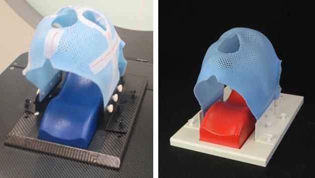
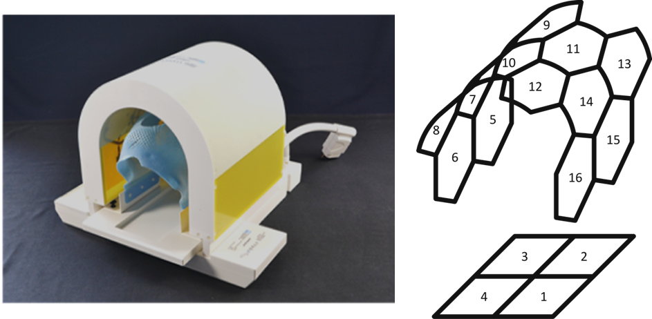
Figure 1 (left) shows the positioning setup on the treatment couch. The individual prepared mask is fixed on a base plate for patient immobilization. In a first step, all conductive materials had to be replaced by non-conductive material (PVC, right) to ensure patient safety. A tunnel-shaped coil arrangement, consisting of a base plate and horseshoe-shaped attachment which can be moved in head-foot direction was then built around the mask (Fig. 2 left). 16 equally sized coil elements were distributed in these two parts (Fig. 2, right). The structure of each coil element consist of the typical components “tune and match”, active decoupling, standing wave blocking in the supply line and fuse protection for the first error case. The workbench performance of the coil was evaluated by a network analyzer (Agilent) the Q factor ratio (unloaded/loaded) and the decoupling amongst coil elements. Phantom and volunteer measurements were performed on a 1.5T Siemens Avanto. The noise correlation matrix was calculated to investigate independent performance of individual channels. Additionally, SNR cards were calculated with a SOS and Root SOS combination of the coil elements 6,7.Results and Discussion
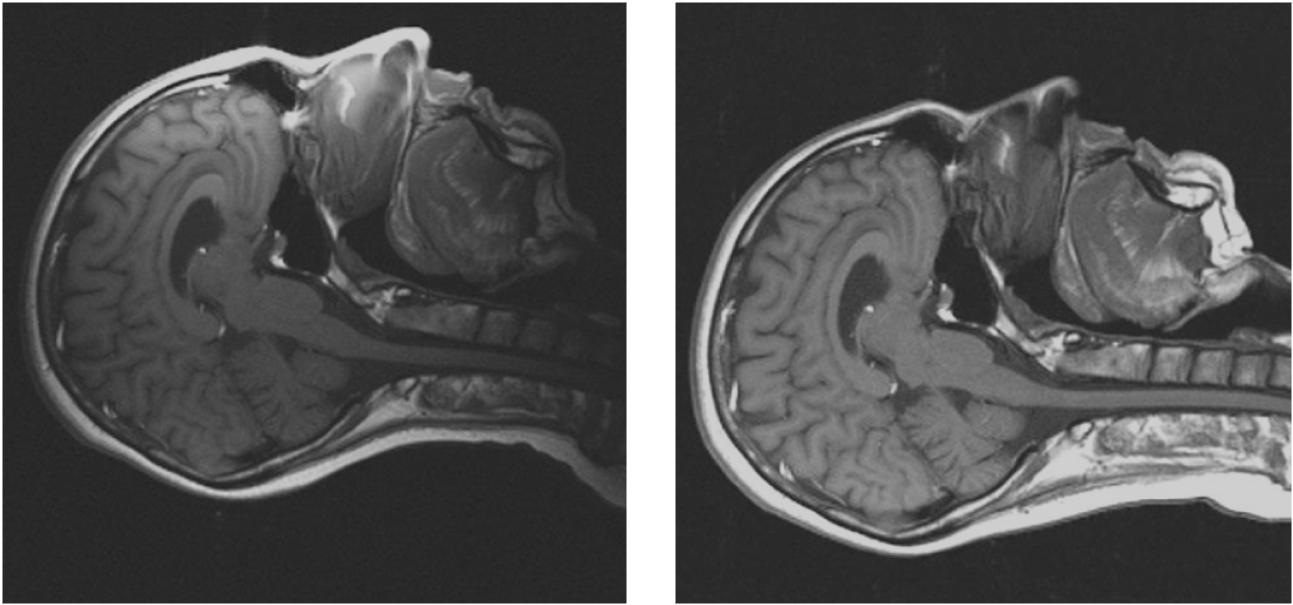
The design of the coil allows for the examination of patients in treatment position (with mask) without contact to the coil. On the workbench, the typical Q ratio is 1.4 of the base plate coil elements (unloaded to loaded) and 3.0 of the tunnel elements which shows that coil noise is dominant. This is due to the relatively high distance between coil elements and tissue under investigation. This distance results from the need of the radiation treatment mask. S parameter measurements show that S12 between individual coil elements is better than -20dB, proving good isolation of coil channels. In the MR, the noise correlation matrix shows a mean correlation of 12% and a maximum of 42% (Fig. 3) which is acceptable for good SNR. The resulting SNR card for different reconstruction algorithms of a transversal slice of the phantom are displayed on the left side in Fig. 3. The mean SNR of the marked central area was 114 for the RSS and 106 for the SOS combination, showing almost no difference which confirms the good noise correlation performance. Figure 4 shows a comparison of the same sagittal slice acquired with the proposed coil in treatment position (left) and the standard head and neck coil in predetermined position. The standard coil shows a better image quality in terms of image signal. However, anatomical differences especially in the neck region can be clearly seen.Conclusion
In this work, a novel 16 channel head and neck array coil is presented, which is adapted to the special requirements of radiotherapy planning. It allows for MR imaging of patients with brain and head and neck tumors in CT planning and treatment position. Uncomfortable positioning can be avoided because the patient is first fixed on the base plate and the tunnel-shaped arrangement is imposed subsequently. Additionally, follow-up examinations can be performed in reproducible position. In future work, the image quality of the proposed coil and the performance of the fusion between the treatment planning CT and MR data sets acquired with standard and the presented coil will be investigated in a preclinical trial.Acknowledgements
No acknowledgement found.References
1. Siebers JV, Keall PJ, Wu Q, Williamson JF, Schmidt-Ullrich RK: Effect of patient setup errors on simultaneously integrated boost head and neck IMRT treatment plans. Int J Radiat Oncol Biol Phys 2005, 63:422-433.
2. Liney GP, Moerland MA: Magnetic resonance imaging acquisition techniques for radiotherapy planning. Semin Radiat Oncol 2014, 24:160-168.
3. Schmidt MA, Payne GS: Radiotherapy planning using MRI. Phys Med Biol 2015, 60:R323-361.
4. Chuter R, Prestwich R, Bird D, Scarsbrook A, Sykes J, Wilson D, Speight R: The use of deformable image registration to integrate diagnostic MRI into the radiotherapy planning pathway for head and neck cancer. Radiother Oncol 2017, 122:229-235.
5. Hanvey S, McJury M, Tho LM, Glegg M, Thomson M, Grose D, James A, Rizwanullah M, Paterson C, Foster J: The influence of MRI scan position on patients with oropharyngeal cancer undergoing radical radiotherapy. Radiat Oncol 2013, 8:129.
6. Kellman P, McVeigh ER: Image reconstruction in SNR units: a general method for SNR measurement. Magn Reson Med 2007,54(6):1439-47
7. Robson PM, Grant AK, Madhuranthakam AJ, Lattanzi R, Sodickson DK, McKenzie CA: Comprehensive Quantification of Signal-to-Noise Ratio and g-Factor for Image-Based and k-Space-Based Parallel Imaging Reconstructions: Magn Reson Med 2008, 60(4): 895–907.
Figures