1496
Radiofrequency applicator concepts for RF hyperthermia treatment and MR imaging of glioblastoma multiforme at 7.0 T (298 MHz)1Berlin Ultrahigh Field Facility (B.U.F.F.), Max Delbrueck Center for Molecular Medicine in the Helmholtz Association, Berlin, Germany, 2MRI.TOOLS GmbH, Berlin, Germany, 3Clinic for Radiation Oncology, Charite University Medicine, Berlin, Germany, 4Experimental and Clinical Research Center (ECRC), a joint cooperation between the Charité Medical Faculty and the Max Delbrueck Center for Molecular Medicine in the Helmholtz Association, Berlin, Germany
Synopsis
Glioblastoma multiforme is the most frequent and most aggressive malignant brain tumor with de facto no prognosis of long-term survival by the use of current multimodal therapeutic approaches. RF heating at ultrahigh fields (B0=7.0T, f=298MHz) has the potential of delivering sufficiently large thermal dosage for hyperthermia of relatively large tumor areas. This work focuses on EMF simulations and compares RF applicator designs tailored for simultaneous RF heating and MRI. Our results suggest that RF power can be focused to small tumor areas and to large clinical target volumes derived from segmented patient data.
Purpose
Glioblastoma multiforme is the most frequent and aggressive malignant brain tumor with no prognosis of long-term survival by the use of multimodal therapeutic approaches1. A study showed the principal effectiveness of brachytherapy and enhancing interstitial hyperthermia, prolonging median survival2. The invasiveness of this approach is a major drawback for wide clinical application and constitutes the need for non-invasive thermal therapy. Simultaneous RF-heating and MRI at ultrahigh fields (B0=7.0T, f=298MHz)3-7 has the potential of delivering sufficiently large thermal dosage for hyperthermia of relatively large tumor areas. In this work we present RF applicators tailored for simultaneous RF-heating and MRI to combine diagnosis (MRI), treatment (RF-hyperthermia) and real-time therapy control (MR thermometry). En route to RF-induced hyperthermia treatment of glioblastoma in the human brain, this work focuses on electromagnetic field (EMF) simulations that incorporate clinical data obtained from glioblastoma multiforme patients.Methods
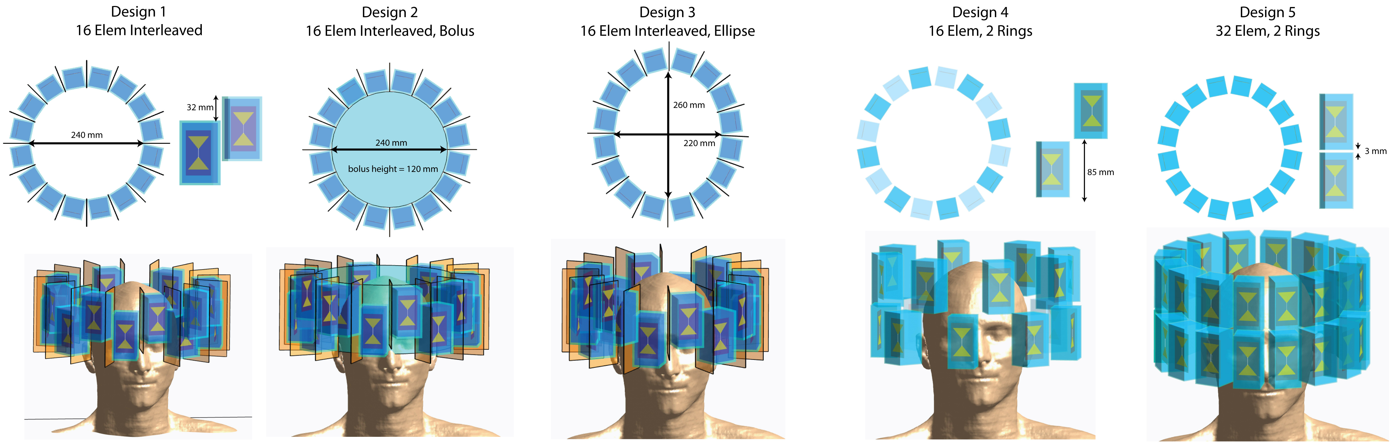
The proposed applicator configurations are composed of 16 to 32 bow-tie dipole building blocks8 placed in one or two rings around the head (Figure1). EMF simulations9 were performed to examine i) head coverage along the head-feet-direction, ii) number of elements, iii) elliptical antennae arrangement and iv) presence of a water bolus, compared to a reference design8 (Design1). SAR-based RF-hyperthermia planning8 was applied for each applicator design and voxel model. To advance the EMF simulations to a clinical setup, two tumor models were incorporated: (i) voxel model ‘Duke’10 with a small spherical (Ø=4cm) tumor, (ii) voxel model of a patient with a glioblastoma multiforme derived from a clinical CT scan.
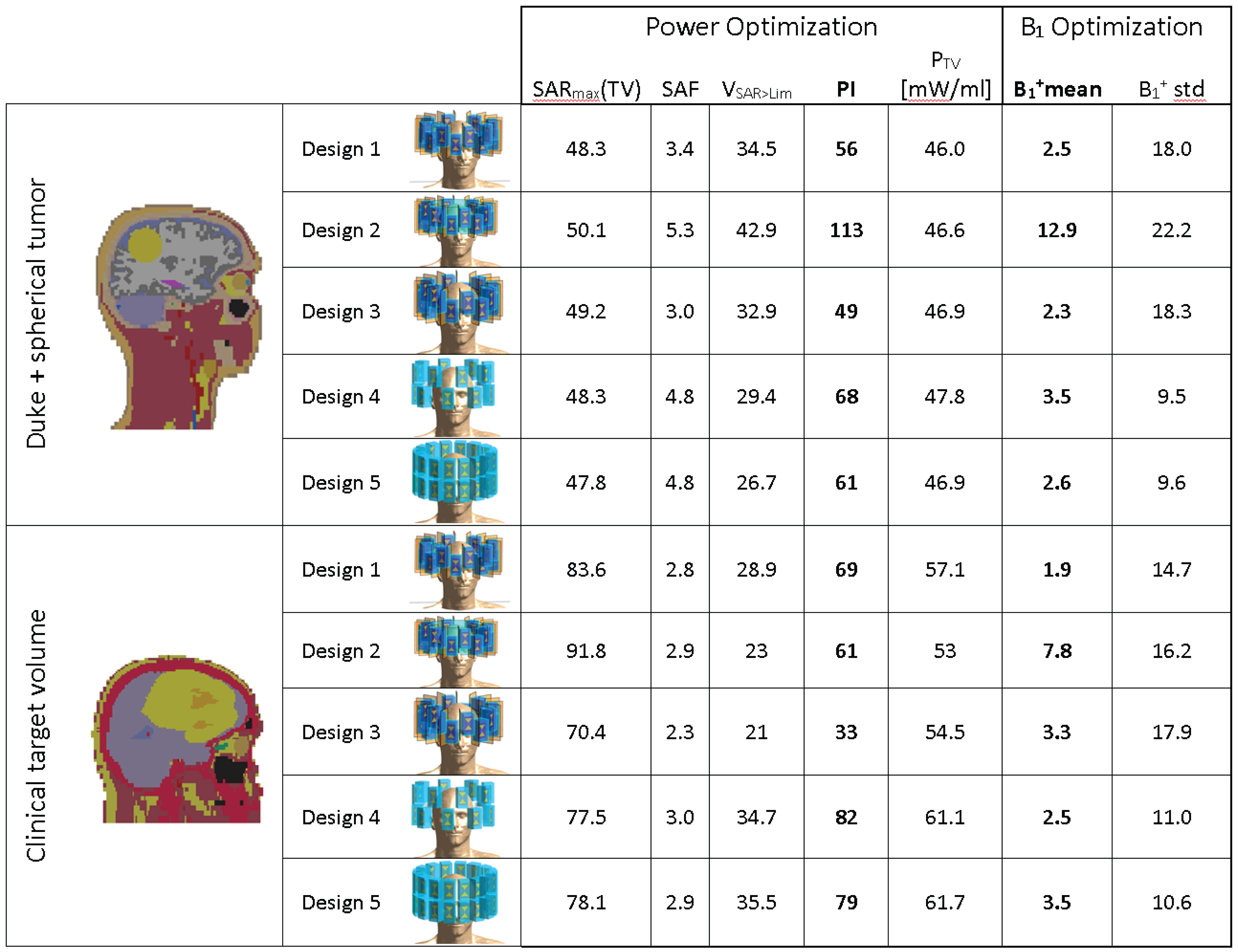
For SAR-based RF-hyperthermia planning, isotropically re-binned11 SAR10g12 data and VOPs13 were calculated14. The optimization goal is set to maximize total power absorption in the target volume (TV) under the constraint of a SAR10g,max in the healthy tissue8. For analysis of the optimization performance, we assessed i) SAR10g,max and ii) SAR10g,mean in the TV, iii) the SAR amplification factor SAF=SAR10g,mean(TV)/SAR10g,mean(healthy) and iv) the volume of the TV exposed to a higher SAR10g than the healthy tissue limit (VSAR>Lim). To get a combined measure for a high SAR increase in combination with a good coverage of the TV while sparing the healthy tissue, we introduced the performance indicator PI=SAR10g,max(TV)·SAF·VSAR>Lim.
To demonstrate that the applicators equally support MRI and thermometry, B1 maps were calculated. For this purpose, the identically re-gridded non-combined H-field data was normalized to Pin=1W peak power accepted at port. A magnitude least square phase and amplitude B1+ shimming15 was performed12 for a ROI covering the brain.
Results
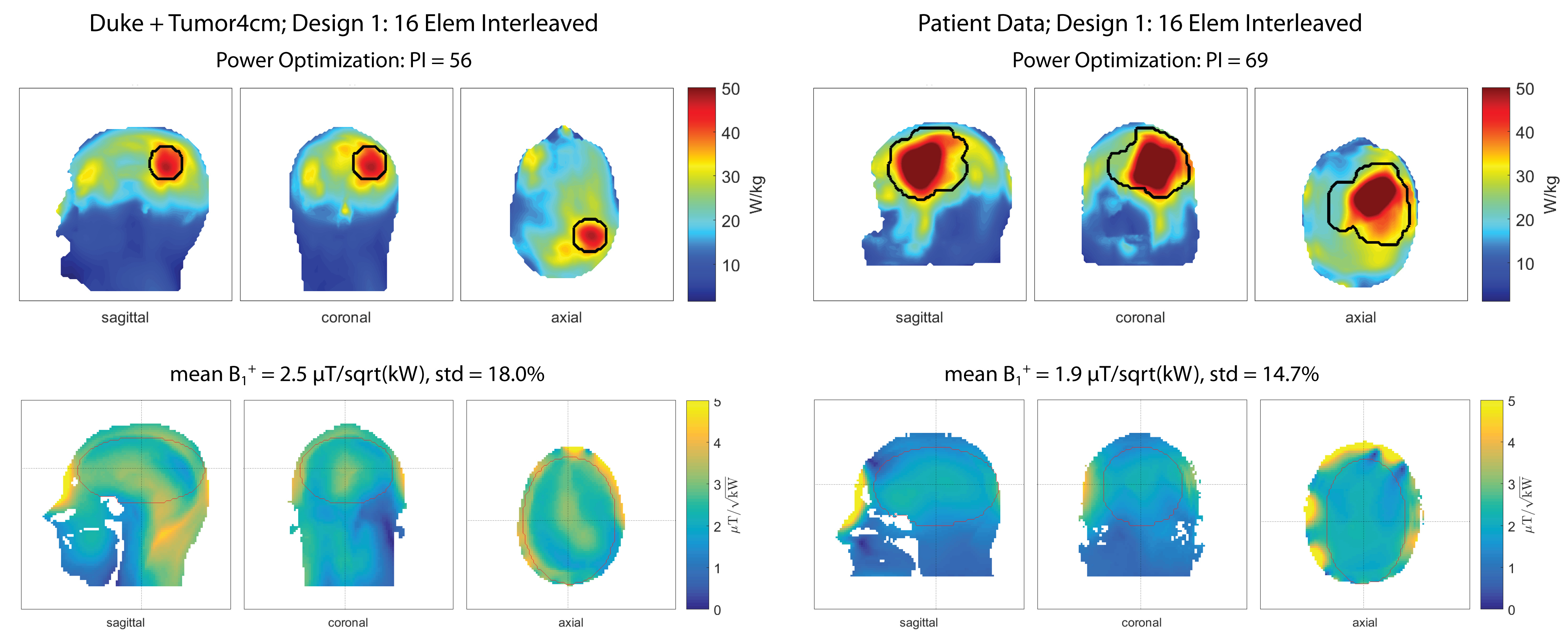
Figure2 shows the SAR10g and B1+ maps for Design1 (Duke: PI=56, B1+mean=2.5µT/sqrt(kW); Patient: PI=69, B1+mean=1.9µT/sqrt(kW), Table1). The limited number of segmented tissue types and the limited geometrical extend of the patient voxel model results in different loading conditions which can explain the different B1+-values.
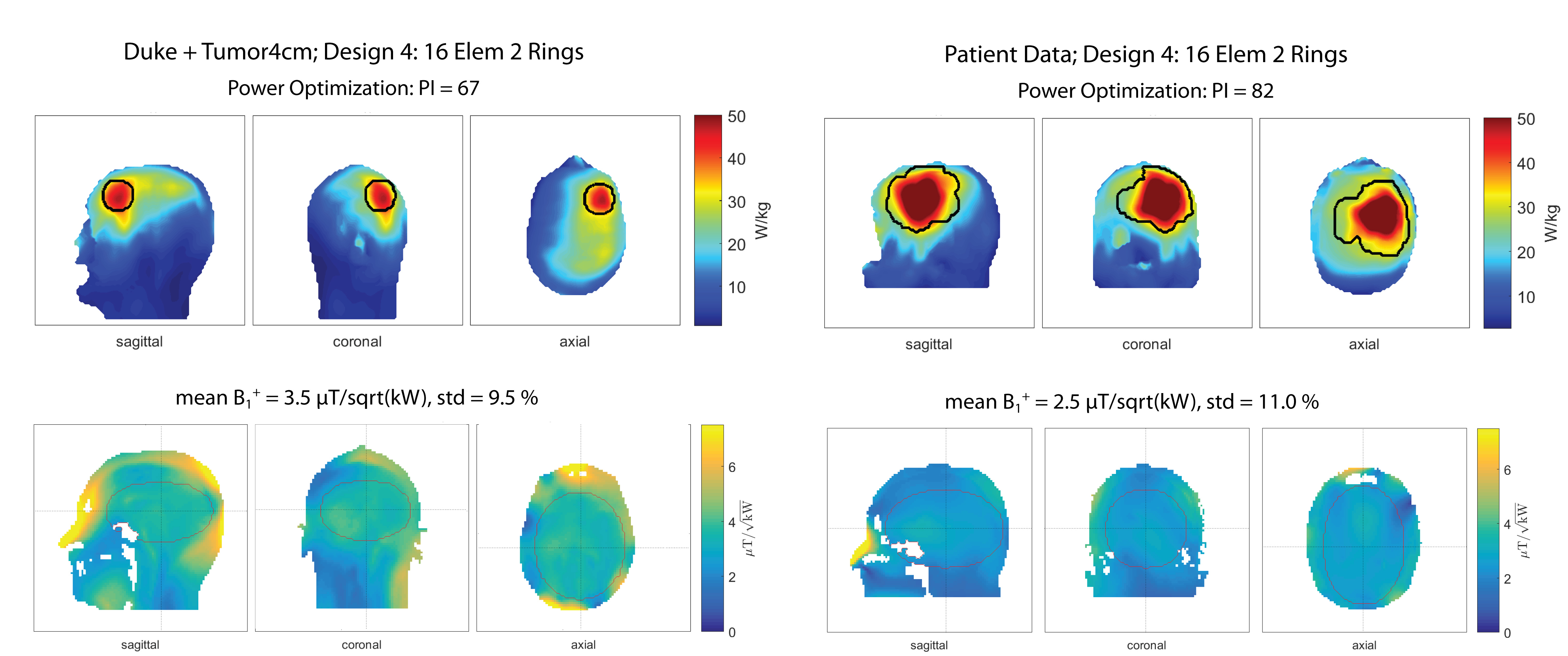
Head coverage, RF-hyperthermia and B1+ optimization performances were improved by arranging the 16 elements in two separate rings (Design4) rather than interleaved (Duke: PI=68, B1+mean=3.5µT/sqrt(kW); Patient: PI=82, B1+mean=2.5µT/sqrt(kW)), as shown in Figure3. Design4 provided the best results among all designs without a water bolus (Table1).
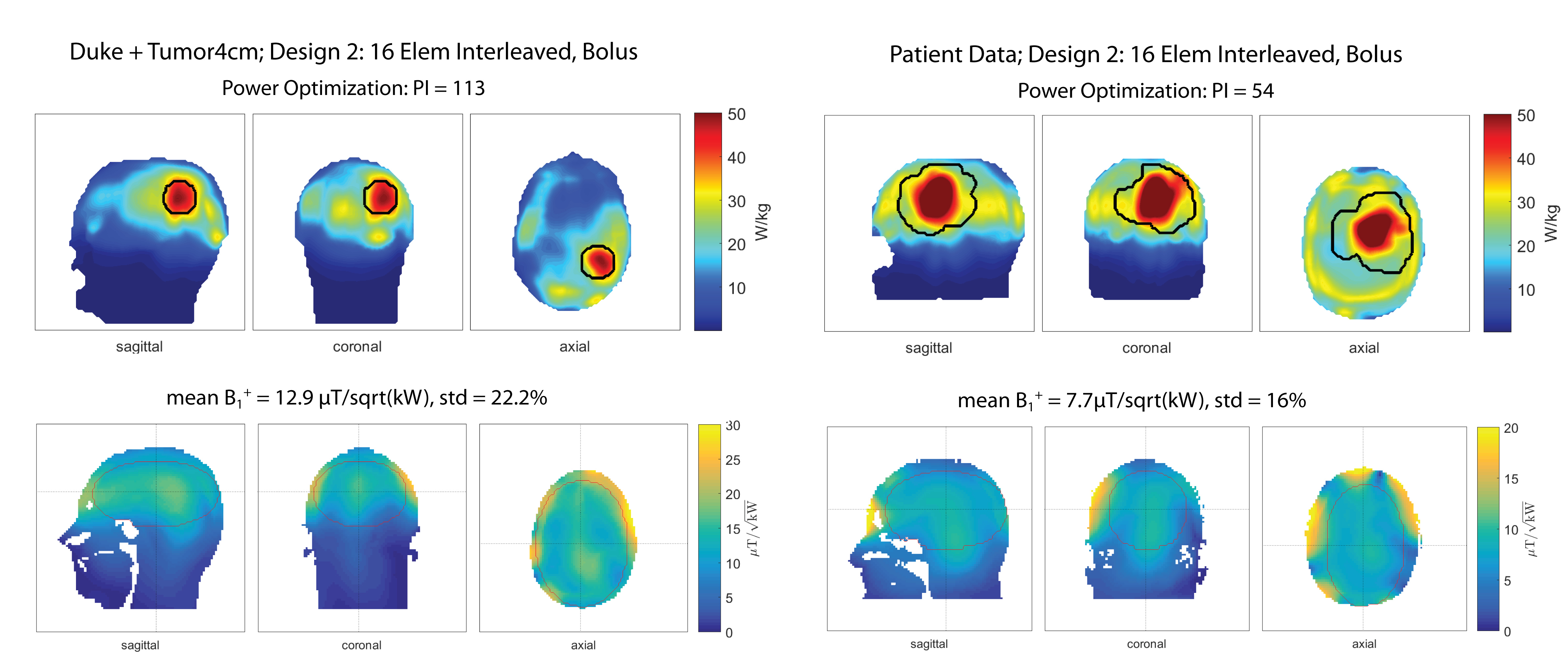
Presence of a water bolus (Design2) substantially improved RF applicator performance for voxel model Duke (Figure4). The PI of 113 is doubled compared to the same antenna arrangement without bolus (Design1). The mean B1+ in the ROI of 12.9µT/sqrt(kW) is comparable with commercially available head coils at 7.0T and is sufficient to obtain a flip angle of 180° for a 1ms pulse16. For the patient voxel model the water bolus improved B1+mean substantially, however did not show improvements in terms of tumor power absorption (Table1).
Discussion and Conclusion
Our numerical EMF simulations included brain tumors and target volumes which were derived from clinical radiation therapy planning data. We demonstrated that the proposed RF applicator designs perform better than the reference design. Increasing the brain coverage resulted in a higher benefit than just increasing the number of input channels for the same coverage.
To conclude, our explorations showed how to adapt RF applicators to generate heat in clinical target volumes by using 2D high-density RF antenna arrays. Bigger tumors might benefit from a different water bolus design or antenna placement that not only improves B1+ as demonstrated but also provides more uniform power deposition over the target volume. Moving from SAR to temperature optimization in a next step will enable new insights into further improving the RF applicator performance. Empowered by these insights and novel RF applicator designs, we endeavor to take it to the next level by implementing the proposed configurations on a 7.0T MR system.
Acknowledgements
This work was supported in part (L.W., E.O., J.N., A.K., T.N., H.W.) by the German Federal Ministry of Education and Research, “KMU-innovativ”: Medizintechnik 13GW0102.References
1. World Cancer Report 2014. World Health Organization. 2014. pp. Chapter 5.16. ISBN 9283204298.
2. P. K. Sneed, P. R. Stauffer, M. W. McDermott, C. J. Diederich, K. R. Lamborn, M. D. Prados, S. Chang, K. A. Weaver, L. Spry, and M. K. Malec, "Survival benefit of hyperthermia in a prospective randomized trial of brachytherapy boost+/-hyperthermia for glioblastoma multiforme," Int J Radiat Oncol Biol Phys, vol. 40, pp. 287-295, 1998.
3. L. Winter, C. Özerdem, W. Hoffmann, D. Santoro, A. Müller, H. Waiczies, R. Seemann, A. Graessl, P. Wust and T. Niendorf, Design and Evaluation of a Hybrid Radiofrequency Applicator for Magnetic Resonance Imaging and RF Induced Hyperthermia: Electromagnetic Field Simulations up to 14.0 Tesla and Proof-of-Concept at 7.0 Tesla. PLoS One, 2013. 8(4): p. e61661.
4. L. Winter, C. Oezerdem, W. Hoffmann, T. van de Lindt, J. Periquito, Y. Ji, P. Ghadjar, V. Budach, P. Wust and T. Niendorf, Thermal magnetic resonance: physics considerations and electromagnetic field simulations up to 23.5 Tesla (1GHz). Radiation Oncology, 2015. 10(1): p. 1.
5. B. Guerin, J.F. Villena, A.G. Polimeridis, E. Adalsteinsson, L. Daniel, J.K. White, B.R. Rosen and L.L. Wald, Ultimate hyperthermia: Computation of the best achievable radio-frequency hyperthermia treatments in non-uniform body models, Proceedings of the 24th ISMRM, 2015
6. Pendse M and Rutt B, An algorithm for maximum-SAR Targeted RF Hyperthermia, Proceeding of 24th ISMRM annual meeting, 2015
7. M.A. Ertürk, S.S. Hegde and P.A. Bottomley, Radiofrequency Ablation, MR Thermometry, and High-Spatial-Resolution MR Parametric Imaging with a Single, Minimally Invasive Device. Radiology, 2016: p. 151447.
8. E. Oberacker, A. Kuehne, H. Waiczies, J. Nadobny, M. Weihrauch, S. Zschaeck, P. Ghadjar, P. Wust, T. Niendorf and L. Winter, Radiofrequency applicator concepts for simultaneous MR imaging and hyperthermia treatment of glioblastoma multiforme: A 7.0 T (298 MHz) study. Proceeding of 26th ISMRM annual meeting, 2017
9. Sim4Life V2.0, ZurichMedTech, Zurich, Switzerland
10. ITIS foundation, Zurich, Switzerland
11. Volken W, Frei D, Manser P, Mini R, Born EJ, Fix MK. An integral conservative gridding--algorithm using Hermitian curve interpolation. Phys. Med. Biol. 2008;53:6245–63. doi: 10.1088/0031-9155/53/21/023.
12. Kuehne A, Seifert F, Ittermann B. GPU-accelerated SAR computation with arbitrary averaging shapes. In: Proceedings of the ISMRM. Melbourne, Australia; 2012. p. 4260.
13. G. Eichfelder and M. Gebhardt, Local specific absorption rate control for parallel transmission by virtual observation points. Magnetic Resonance in Medicine, 2011. 66(5): p. 1468-1476.
14. The MathWorks Inc., Natick, Massachusetts, US
15. Setsompop, K., Wald, L.L., Alagappan, V., Gagoski, B.A. and Adalsteinsson, E. (2008), Magnitude least squares optimization for parallel radio frequency excitation design demonstrated at 7 Tesla with eight channels. Magn. Reson. Med., 59: 908–915. doi:10.1002/mrm.21513
16. Vaughan, J.T., Garwood, M., Collins, C.M., Liu, W., DelaBarre, L., Adriany, G., Andersen, P., Merkle, H., Goebel, R., Smith, M.B. and Ugurbil, K. (2001), 7T vs. 4T: RF power, homogeneity, and signal-to-noise comparison in head images. Magn. Reson. Med., 46: 24–30. doi:10.1002/mrm.1156
Figures