1488
A hardware and algorithm framework for focal spot and slice positioning in MRgFUS treatments1Utah Center for Advanced Imaging Research (UCAIR), University of Utah, Salt Lake City, UT, United States
Synopsis
MRgFUS systems can be designed with a high degree of transducer positioning variability for precise focal point placement during tissue ablation procedures. This study evaluates hardware design and complementary algorithmic adaptations that predict the focal spot location and MRI slice orientation as a function of transducer adjustment settings. These design features were evaluated by comparing the physical focus of a mock transducer to the computed focus location from the prediction algorithm. The mean error between the measured and predicted point position was found to be 2.9±1.8mm (N=20). Predicted slice orientation parameters also showed good agreement with hardware adjustment measurements.
Introduction
MRI is used in all aspects of magnetic resonance guided focused ultrasound (MRgFUS) treatments. Treatment planning steps typically include localizing the focused ultrasound beam and accurately placing the MRI slices used to monitor the temperature response of tissue in real time. These steps are often iterative and can lead to increased treatment times. When transducers can be placed with multiple degrees of freedom, this step can increase in complexity. This work describes hardware and algorithmic adaptations that have been integrated in a breast-specific MRgFUS system in order to automatically address the issues of accurate focal spot positioning, MRI slice placement and repositioning.Methods
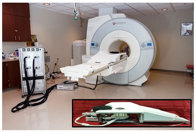
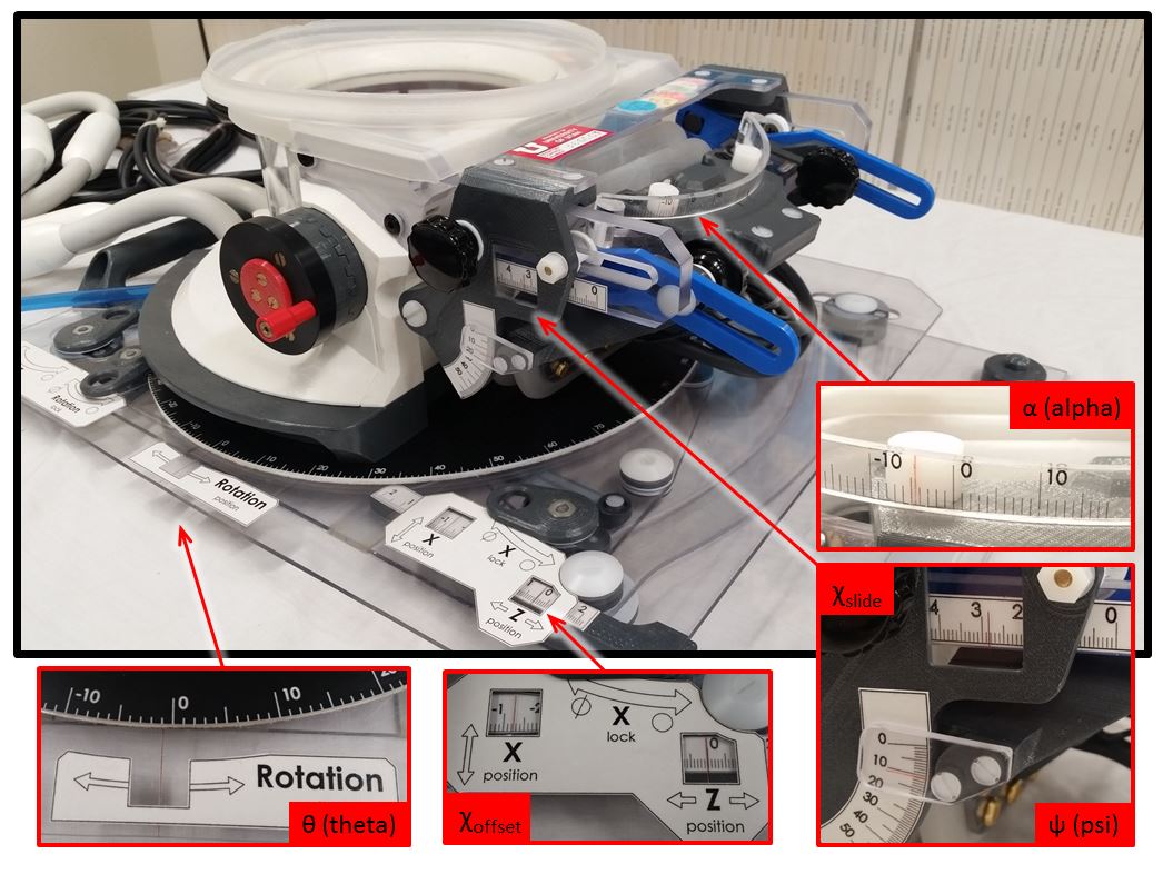
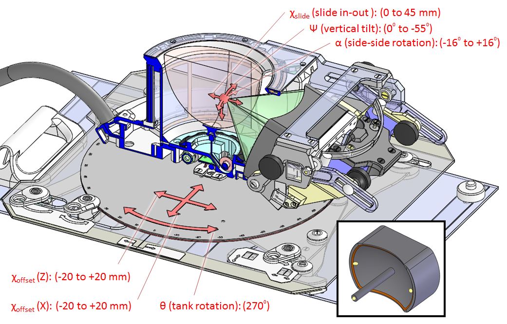
Positioning hardware: The breast-specific MRgFUS system (1,2) shown in Figure 1 is a modular design that allows for a large degree of transducer positioning variability. The system consists of a treatment cylinder, positioning trolley, adjustable headrest and patient support table. The phased-array ultrasound transducer is mounted laterally on the treatment cylinder that is atop the positioning trolley that allows the cylinder to translate and rotate under the patient. Transducer positioning is achieved through visual indicators on the treatment cylinder and positioning trolley (Fig. 2) that allow for a positioning accuracy of ±1° and ±1 mm in rotational and translational movements, respectively. The transducer has a total of six degrees of freedom (Fig. 3).
Positioning algorithm: After an initial calibration procedure, a transformation algorithm is used to determine the position of the geometric focus in MRI coordinates: $$$ \overrightarrow{\chi_{MRI}}=\overrightarrow{\chi_{offset}}-\overrightarrow{\chi_{trolley}}+R_{\theta}(\overrightarrow{\chi_{slide}}-\overrightarrow{\chi_{cent}}+R_{\psi}R_{\alpha}\overrightarrow{\chi_{focus}}) $$$. The algorithm takes as input the hardware adjustment data consisting of gauge readings in millimeters or degrees $$$ (\overrightarrow{\chi_{trolley}}, R_{\theta},\overrightarrow{\chi_{slide}}, R_{\psi}, R_{\alpha}) $$$. Twenty different hardware adjustment vectors were studied in this work. Other inputs $$$ (\overrightarrow{\chi_{cent}},\overrightarrow{\chi_{focus}}) $$$ are constants derived from physical dimensions of the hardware (i.e. transducer focal length). The algorithm outputs the predicted focus location as standard MR coordinates: Left/Right, Anterior/Posterior, Head/Foot. A calibration offset $$$ (\overrightarrow{\chi_{offset}}) $$$ maps the treatment cylinder center to the MRI landmark position. The algorithm also computes MR position and orientation for slices that are parallel with or orthogonal to the FUS beam direction.
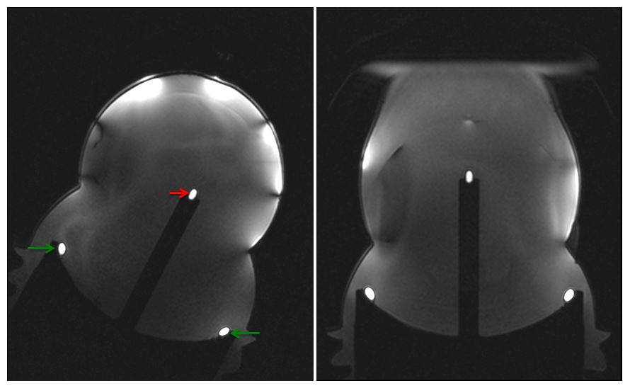
Algorithm validation was performed by replacing the functioning transducer with a printed facsimile transducer with fiducial beads fixed at the geometric focus and transducer midplane (Fig. 3). For the 20 experiments, transducer adjustments were set to arbitrary values and input to the positioning algorithm. For each position, images were obtained using a 3D GRE sequence (TR/TE=7/1.3ms, FA=20°, FOV=256x192x96mm, resolution=0.5x0.5x1mm, BW=445 Hz/pixel, 3T Prisma, Siemens, Erlangen, Germany) and MR coordinates of the center voxel of the bead were recorded. For the various combinations of system translations and rotations, the measured and algorithm-predicted coordinates were compared to determine the precision of hardware adjustments.
Results
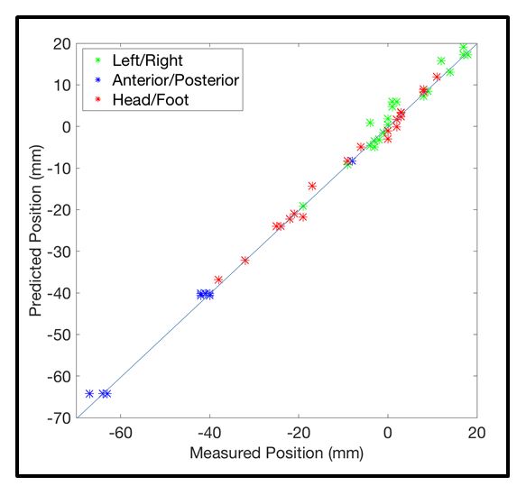
The mean error between the predicted and measured focal point position using the developed hardware and algorithm was found to be 2.9±1.8mm (N=20). A comparison of the predicted and the measured position for the three standard MRI coordinates is seen in Figure 4. All three directions are in good agreement. Figure 5 demonstrates the algorithm’s ability to calculate oblique coronal MRI slice position. Oblique axial and sagittal slice orientations are also predicted.Discussion & Conclusion
While having an MRgFUS system with variable transducer positioning can offer increased flexibility during treatments, it complicates patient positioning, focal spot location, MR slice assignment and patient repositioning. Because this system currently requires manual manipulation of all degrees of freedom, operator error in reading and recording values is a major consideration in the precise positioning of the focal point. Enlarging hardware gauges to improve readability could reduce this error.
Although the prediction algorithm in this work was used to compute focal point coordinates in image space from a known set of hardware adjustments, it will be applied iteratively in the future to explore hardware adjustment combinations to achieve both safe skin entry trajectories and accurate focal targeting at a desired MR coordinate. This valuable information would be essential for both treatment planning and any necessary patient repositioning.
The MRgFUS system presented in this work also has RF positioning coils for automatic focal point determination (3) that have a demonstrated accuracy of 2.1±1.1mm when compared to the resulting heating location. While these coils are very useful for determining the focal spot position, they offer no information regarding transducer positioning. The algorithm presented in this work will fill the need of providing positioning information that will aid in both treatment planning and execution.
Acknowledgements
Funding received from grant, NIH RO1 CA172787.References
1. Payne A, Merrill R, Minalga E, Vyas U, de Bever J, Todd N, Hadley R, Dumont E, Neumayer L, Christensen D, Roemer R, Parker D. Design and characterization of a laterally mounted phased-array transducer breast-specific MRgHIFU device with integrated 11-channel receiver array. Med Phys. 2012;39(3):1552-60. doi: 10.1118/1.3685576. PubMed PMID: 22380387; PMCID: 3306440.
2. Minalga E, Payne A, Merrill R, Todd N, Vijayakumar S, Kholmovski E, Parker DL, Hadley JR. An 11-channel radio frequency phased array coil for magnetic resonance guided high-intensity focused ultrasound of the breast. Magn Reson Med. 2013;69(1):295-302. doi: 10.1002/mrm.24247. PubMed PMID: 22431301; PMCID: 3382025.
3. Svedin BT, Beck MJ, Hadley JR, Merrill R, de Bever JT, Bolster BD, Jr., Payne A, Parker DL. Focal point determination in magnetic resonance-guided focused ultrasound using tracking coils. Magn Reson Med. 2016. doi: 10.1002/mrm.26294. PubMed PMID: 27418429.
Figures