1487
The effect of transducer position on signal-to-noise ratio in magnetic resonance guided focused ultrasound1Utah Center for Advanced Imaging Research, University of Utah, Salt Lake City, UT, United States
Synopsis
Hardware requirements can be a roadblock to implementing procedure-specific coils in magnetic resonance guided focused ultrasound. In order to more effectively implement coils in the system, the effects of the focused ultrasound transducer’s position on SNR needs to be considered. This work characterizes the SNR and noise correlation variability of the RF coils by evaluating the SNR tradeoffs and noise correlation as a function of device orientation and transducer position and report such variances. Understanding the SNR tradeoffs of system placement during treatment can aid in increased SNR within the treatment volume and can be a factor to consider in treatment planning.
Introduction
Due to the hardware requirements of magnetic resonance guided focused ultrasound (MRgFUS), procedure-specific coils are not often used. As RF coil integration advances in this field, effects of the focused ultrasound transducer’s position on SNR need to be considered. The Muse MR guided focused ultrasound (FUS) treatment device and associated radio frequency (RF) coils (1-7) is a breast-specific design that allows for rotation of the entire device and variable transducer positioning to target tumors throughout the breast. The system adjustability results in potential variations in SNR and noise correlation due to reduced signal sensitivity and shielding of the RF coils by the solid transducer ground plane (8). This work characterizes the SNR and noise correlation variability of the RF coils by evaluating the SNR tradeoffs and noise correlation as a function of device orientation and transducer position. Accurate characterization of device-position dependent SNR variability could be potentially used during patient treatment planning. Such information could be used to adjust pulse sequence parameters to improve treatment plans and monitoring techniques to compensate for any expected SNR reduction.Methods
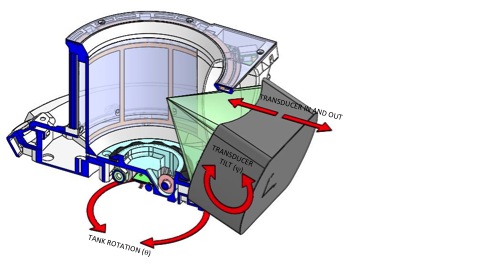
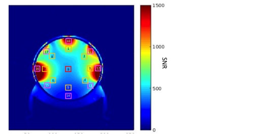
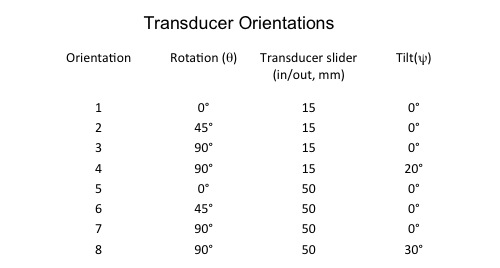
A cross-sectional view of the Muse MRgFUS device is shown in Fig.1A. The transducer is 256-element phased array with a 14.5x8 cm aperture size and conductive ground plane (Imasonics, Inc., Bensacon, France). The 5 degree-of-freedom mechanical steering and volumetric electrical steering results in 1001 cm3 a treatment volume. The treatment cylinder (14cm diameter, 11cm height) integrates an 8-channel RF imaging coil array. A six channel ladder geometry (9,10) phased array (11) is wrapped around the cylinder (elements 5cm wide x 9cm high), a 17 cm diameter chest loop coil encircles the top of the cylinder, and a 10cm x 15cm loop surrounds the transducer opening. To test for variations in RF coil performance with device position and transducer orientation, coronal SNR scans (GRE: TR/TE 500/10ms, flip angle=90°, FOV=256x256mm, Resolution=1x1x5mm, 5 Averages) were taken of a homogeneous Cu2SO4 cylindrical phantom at 8 different transducer positions. The transducer rotation, slider position and tilt values are summarized in Table 1. SNR and noise correlation were calculated for each treatment configuration using methods published previously. SNR measurements were obtained from seventeen ROIs distributed throughout the phantom (see Fig.2 and Fig.3). One ROI was at the center of the treatment tank and 2 sets of eight were placed radially at a distance of 40 and 55 mm from the treatment cylinder center.Results
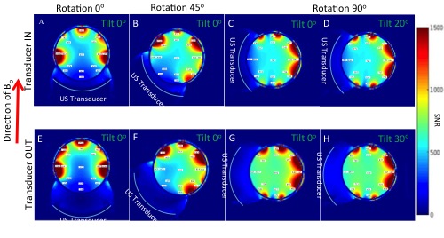
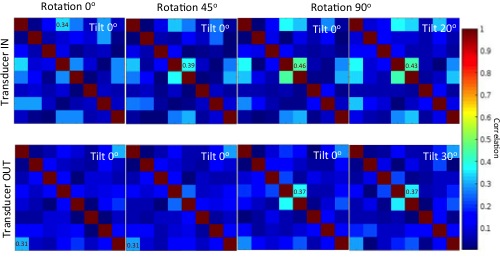
SNR images at the 8 orientations are shown in Fig.3. The largest variation in SNR occurs with rotation angle, with the largest variance occurs towards the edge of the cylinder. When the system was rotated the average percent change of all the ROIs was 53.5%(compare Fig.3A and Fig.3E). The SNR at the center of the phantom varies from 372 (Fig.3E) to 692 (Fig.3G). The largest variation is seen at left edge of the tank with a minimum of 330 (Fig.3C) to a maximum of 2148 (Fig.3E). The slider position results in a large change in SNR at the 90° rotation. The smallest variation in SNR results from the transducer tilt; seen when comparing SNR maps Fig.3C to Fig.3D and Fig.3G to Fig.3H in Figure 3 where the average percent change of all the ROIs was 5.2% (compare Fig.3G and Fig.3H). The correlation matrices obtained from each treatment configuration are shown in Fig.4. The highest value for each configuration is indicated in the figure with the max value in any configuration varying from 0.31 to 0.46.Discussion
The Muse MRgFUS system has been engineered to allow treatment from many transducer orientations relative to the breast. Although the SNR variation with rotation is large at the periphery, it is reduced in the center of the treatment cylinder. Therefore SNR variability due to device positioning will likely not impact treatment of centrally located tumors. Conversely, considerations of SNR variability will likely need to be considered in treating tumors closer to the skin. The noise correlation does demonstrate a small change mainly a function of the transducer slide position, but the magnitude of this effect is small enough that it should not affect the overall SNR. Also, as shown in a previous study (8), segmenting the ground plane during the transducer design process would further allow for more stable SNR images as a function of transducer position with the tank.Conclusion
Variations in SNR can impact all aspects of an MRgFUS treatment including planning, temperature monitoring and assessment. Characterization of the SNR profiles in different treatment configurations will allow the use of SNR information to be incorporated into the patient treatment planning process informing treatment configurations selection that provide the best SNR for a given treatment volume.Acknowledgements
Funding received from grant, NIH RO1 CA172787.References
1. Minalga E, Merrill R, Parker DL, de Bever J, Hadley JR, Payne A. Evaluation of a MRgFUS breast system at 1.5 and 3 Tesla.; 2015 April 17, 2015; ISTU; Utrecht, The Netherlands. p Abstract: 2162666
2. Minalga E, Merrill R, Parker DL, Payne A, Hadley JR. Comparison of improved breast magnetic resonance guided focused ultrasound system with improved radio frequency phased array coils. ISMRM. Toronto, Ontario, Canada ; 2015.
3. Minalga E, Merrill R, Todd N, Parker DL, Hadley JR, Bangerter NK. A 10-channel RF coil for use in magnetic resonance guided high intensity focused ultrasound of the brain. 2013; ISMRM; Salt Lake City, Utah. p 0832.
4. Minalga E, Merrill RP, Todd N, Payne A, Parker DL, Hadley JR. A 6-channel brain coil for MR guided high intensity ultrasound. 2012; ISMRM; Melbourne, Australia.
5. Minalga ES, Payne A, Merrill RP, Todd N, Vijayakumar S, Parker DL, Hadley JR. Design and Evaluation of RF Coils for Magnetic Resonance Guided High Intensity Focused Ultrasound. . 2011; ISMRM; Montreal, Canada. p 1726.
6. Payne A, Merrill R, Minalga E, Vyas U, de Bever J, Todd N, Hadley R, Dumont E, Neumayer L, Christensen D, Roemer R, Parker D. Design and characterization of a laterally mounted phased-array transducer breast-specific MRgHIFU device with integrated 11-channel receiver array. Medical physics 2012;39(3):1552-1560.
7. Payne A, Minalga E, Todd N, de Bever J, Dumont E, Neumayer L, Christensen DA, Roemer RB, Parker DL. Initial in vivo evaluation of a breast-specific MRgHIFU system, . 2012; ISMRM; Melbourne, Australia.
8. Minalga E, Payne A, Merrill R, Parker DL, Hadley JR. Effects of ultrasound transducer ground plane configuration on SNR in MR guided focused ultrasound therapies 2017 April 22 - 27, 2017; ISMRM; Hololulu Hawaii. p #783.
9. Jevtic J. Ladder networks for capacitive decoupling in phased-array coils. 2001 21-27 April; ISMRM-ESMRMB Joint Annual Meeting; Glasgow, Scotland, UK. p 17.
10. Wang J. A novel method to reduce the signal coupling of surface coils for MRI. 1996 27 April - 3 May; ISMRM; New York, New York. p 1434.
11. Roemer PB, Edelstein WA, Hayes CE, Souza SP, Mueller OM. The NMR phased array. Magnetic resonance in medicine : official journal of the Society of Magnetic Resonance in Medicine / Society of Magnetic Resonance in Medicine 1990;16(2):192-225.
12. Kellman P, McVeigh ER. Image reconstruction in SNR units: a general method for SNR measurement. Magn Reson Med 2005;54(6):1439-1447.
Figures