1470
Comparison of RF Induced Device Heating at 0.35T and 1.5T1Radiological Sciences, UCLA, Los Angeles, CA, United States, 2Bioengineering, UCLA, Los Angeles, CA, United States
Synopsis
RF induced heating is a safety concern for patients with implanted electronic devices (IEDs). At lower field strengths (0.35T) heating is expected to be lower than at higher field strengths (1.5T). However, little experimental data has been acquired at field strengths below 1.5T. The purpose of this work is to compare the effects of field strength on
Introduction
RF induced heating of implanted electronic devices (IEDs, e.g. pacemakers) remains a significant concern for patients undergoing MRI exams. RF induced heating of IEDs is dependent on many factors, including the amount of applied RF power and the scanner’s center frequency, which is proportional to the B0 field. In the presence of a highly conductive device, RF induced heating is strongly dependent on length-dependent resonant heating of the device that is determined by the Larmor frequency (ω0). Heating effects are proportional to the square of ω0. Therefore, heating is expected to be substantially lower at 0.35T compared to 1.5T, but very little experimental RF induced heating data exists for IEDs at low field strengths. As clinical indications for imaging patients at 0.35T expand due to the availability of new systems (e.g. MRIdian, ViewRay) it is important to explore device heating at this field strength. Therefore, we studied the effect of field strength on RF induced heating by comparing the temperature increase in a standardized titantium rod at 0.35T and 1.5T while controlling the applied B1+RMS.Methods
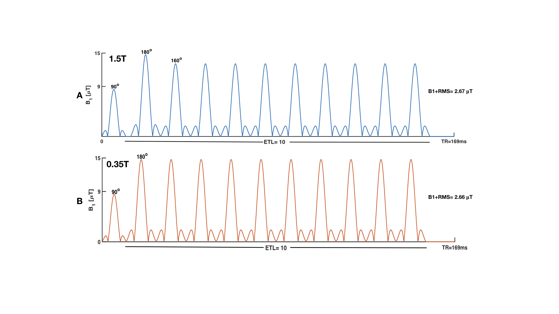
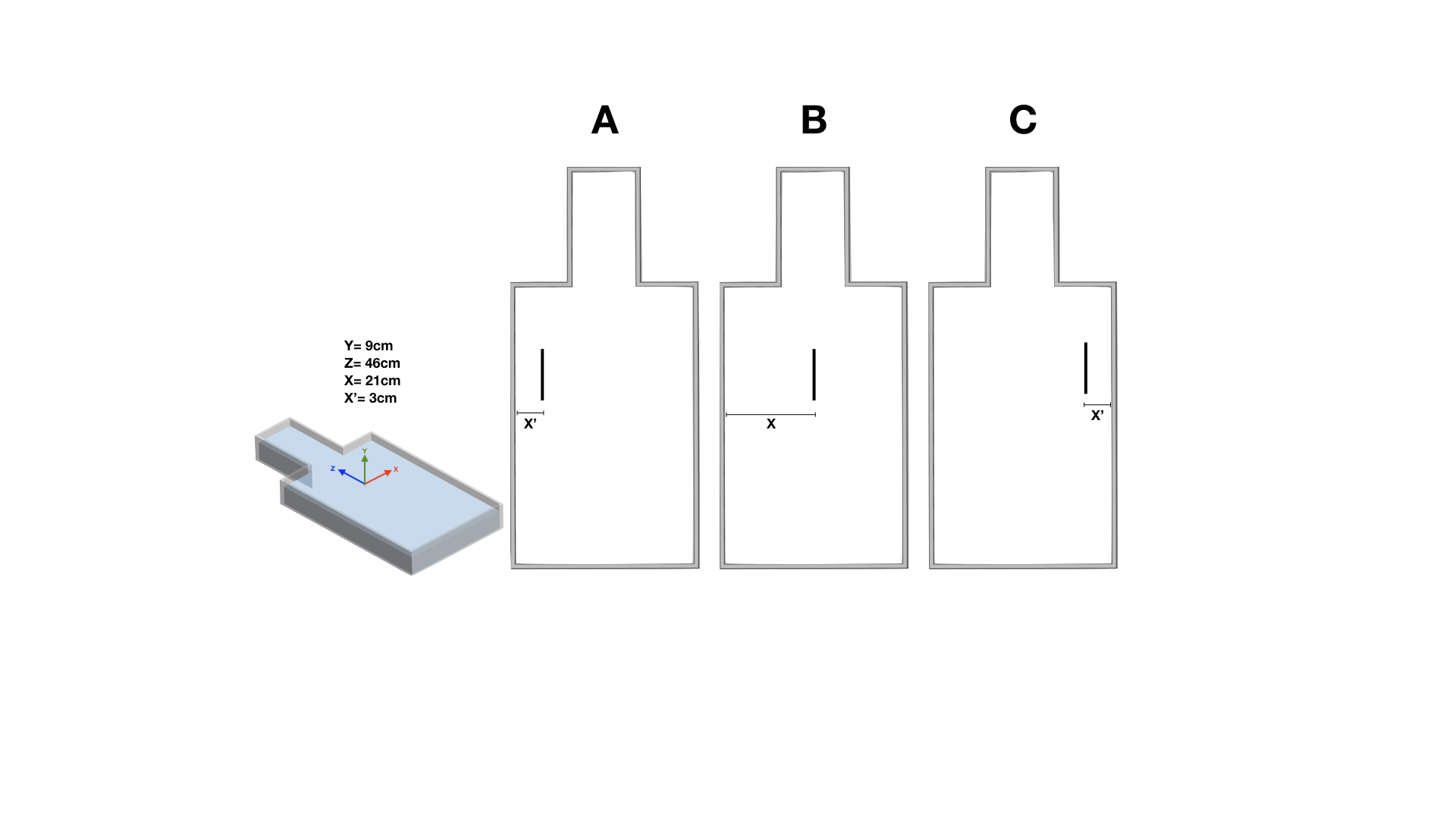
B1+RMS was calculated [1], for a high SAR turbo spin-echo (TSE) sequence using the manufacturer’s pulse sequence simulation software and the extracted RF waveforms for the sequence. RF waveforms are shown in Fig. 1 for 0.35T and 1.5T. Both sequences correspond to a B1+RMS of 2.66µT. This corresponds to SAR≈4W/kg at 1.5T. Following the ASTM guidelines [2], heating experiments used the same B1+RMS and the ASTM torso phantom filled with polyacrylic acid (PAA) with an electrical conductivity of 0.49 S/m. Temperature data were recorded using fiber-optic temperature probes (LumaSense) with a sample rate of 1Hz. The phantom was placed in a head-first orientation at 0.35T (MRIdian, ViewRay) and at 1.5T (Avanto Fit, Siemens) and RF power was applied for 15 minutes to measure temperature increase when a 12-cm titanium rod (long axis parallel to z), was placed at three positions: right (Fig-2A), middle (Fig-2B) and left (Fig-2C). Background temperature increase was measured at the identical location in the absence of the rod.Results
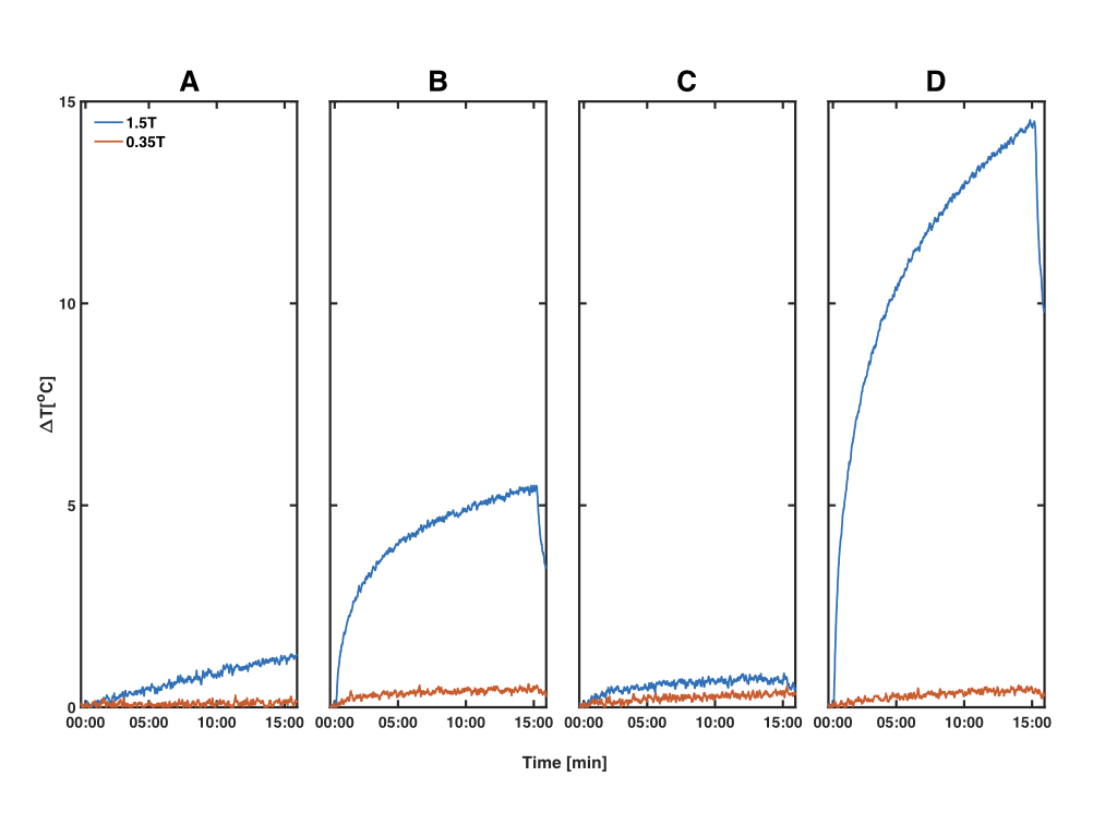
Figure 3 shows the temperature recorded at 0.35T and 1.5T during application 2.66µT B1+RMS. Maximum background heating was 1.3C at 1.5T and 0.3C at 0.35T respectively (Fig. 3A). For the rod, the maximum temperature increase was 5.5°C (right), 0.8°C (middle) and 14.5°C (left) at 1.5T. In contrast the maximum temperature increase was much lower and relatively homogeneous at 0.35T – 0.6°C (right), 0.5°C (middle) and 0.5°C (left).Discussion
As expected, for the same applied B1+RMS, induced heating was substantially lower at 0.35T than at 1.5T. This suggests that patients with IEDs may be scanned at lower field strengths without significant RF induced heating, but more work using IEDs is warranted. At 1.5T, heating was observed to be a function of rod position, which is likely due to the asymmetric E-field. At 0.35T, however, heating was homogeneous and low for the three positions. In addition, further studies are need to be performed with various device lengths and geometries.Acknowledgements
Funding support from NIH/NHLBI R21 HL127433.References
[1] International Organization for Standardization ISO/TS 10974:2012eAssessment of the safety of magnetic resonance imaging for patients with an active implantable medical device.
[2] ASTM F2182-11a, Standard Test Method for Measurement of Radio Frequency Induced Heating On or Near Passive Implants During Magnetic Resonance Imaging, ASTM International, West Conshohocken
Figures