1468
Active Implantable Medical Device – Can its Radio Frequency Radiation be a Potential Source of MR Image Artifact?1Abbott Laboratories, Sylmar, CA, United States
Synopsis
To assess if an active implantable medical device (AIMD) may unintentionally generate radio frequency signals near the receiver band of an MRI RF coil and cause image artifact, a method is proposed in this study to quantify the maximum AIMD radiated signal strength near the MR Lamor frequencies at 1.5T and 3T. Three commercially available AIMDs were investigated and the maximum radiated signal level was found to be around -120 dBm at the 64 and 128 MHz range. Such information can be utilized in conjunction with MR RF receiver specifications to determine the potential impact on image artifacts
Introduction
An active implantable medical device (AIMD) is often designed with wireless communication features. An AIMD can synchronize with external programmer through two types of communication methods: 1) conductive telemetry where low frequency pulses are used to transmit signals via the body tissues to surface-mount electrodes, and 2) radio frequency (RF) telemetry where RF signals are transmitted out of the body via radiation. The general consensus is that no signal leaves the body using the conductive method, while signal is intentionally radiated out of the body using the RF method. With respect to the latter, there is speculation that when a patient with AIMD undergoes MRI scan, if the RF telemetry signal carries frequency components near 63.87 or 127.7 MHz, they may be picked up by the RF receiver coil and contribute to image artifacts.Methods
To investigate if an AIMD may potentially transmit RF signals in the receiver bands of a MRI system, this abstract proposes a method to estimate the AIMD radiated signal strength at MR frequencies. The approach is to first measure AIMD RF transmitter signal near Lamor frequencies, and then based on antenna mismatch and antenna gain, determines the AIMD radiated signal strength at MR frequencies. As the MR RF receiver bandwidth and sensitivity1 are scanner dependent, a 2 MHz bandwidth (± 1 MHz) is considered. The basis of the approach is that no AIMD output signal is expected to be radiated outside of a patient body unless it is mixed with the transmitter (TX) signal and leverages the radiation mechanism of the RF antenna onboard. Furthermore, the onboard RF antenna is tuned to resonate at communication frequency bands only (e.g., Bluetooth around 2.4 GHz or MICS band around 405 MHz), hence any signals outside of the intended communication band will experience high impedance mismatch and poor radiation gain. The final radiated signal level is conservatively calculated by summing the TX signal level, antenna mismatch and antenna gain.Results
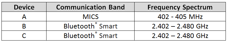
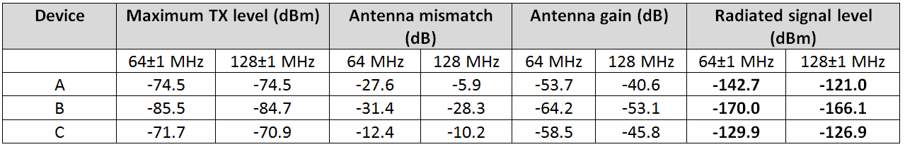
Three commercially available AIMDs, labelled as A, B and C device, are investigated in this work. The communication bands for the aforementioned devices are shown in Table 1. For each device, the transmitter signal level was measured at the MR frequencies with the RF transceiver powered on and in transmit mode. The measured signal level accuracy is at ± 1.00 dbm2. The maximum level in the 63-65 MHz and 127-129 MHz bands are shown in Table 2. The antenna mismatch values at 64 and 128 MHz are calculated using the equation below.
Mismatch Loss = -10*Log (1 - Γ2) where Γ = (Z2-Z1)/(Z2+Z1)
Where Z2 represents the antenna impedance when implanted in tissue and Z1 represents the input impedance looking towards the signal source. The antenna impedance was determined during an in-vivo study where s-parameters measurements were taken at the input to the antenna. The signal source impedance was measured at the input to the RF circuit while the RF transceiver was powered on and in transmit mode. For each device in tissue, the antenna gain simulated using CST Microwave Studio3 at MR frequencies are employed for the final radiated signal level calculation. The radiated signal strengths (sum of TX signal level, antenna mismatch and antenna gain) are shown in Table 2.
Discussion
For the devices under test, the maximum radiated signal level in the MR receiver frequency band was found to be approximately -120 dBm at both 1.5T and 3T. In the worst-case scenario, assuming that a MR surface receiver coil is placed right on top of the AIMD, then the radiated TX signal can be picked up by the receiver without further attenuation or path loss.Conclusion
In this study, we propose a method to quantify the potential interference to MR imaging originated from an AIMD. The basis is that for any non-communication related AIMD outputs (e.g., the therapy outputs) to be radiated out of a body, the only way is through the RF antenna radiation. We measured the TX signals of three commercially available AIMDs and estimated the radiated signal levels at MR frequencies. The maximum signal level was found to be approximately at -120 dBm (10-12 mW) for both the 1.5T and 3T Lamor frequencies. Since the sensitivity and noise floor of a MR receiver coil depends on various factors, e.g., number of signal averages (NSA), etc., the proposed method can be utilized in conjunction with MR RF receiver specifications to determine if AIMD associated RF signal can potentially interfere with MR imaging and cause artifacts.Acknowledgements
No acknowledgement found.References
[1] E. R. McVeigh, M. J. Bronskill, and R. M. Henkelman, Phase and sensitivity of receiver coils in magnetic resonance imaging, Med Phys. 1986; 13(6): 806–814
[2] Keysight Technologies, N9915A FieldFox Handheld Microwave Analyzer, 9 GHz http://www.keysight.com/en/pdx-x201902-pn-N9915A/fieldfox-handheld-microwave-analyzer-9-ghz?cc=US&lc=eng
[3] CST Microwave Studio, https://www.cst.com/products/cstmws
Figures