1459
The feasibility study about the protection circuit for unplugged local transceiver coil in MRI boreSeunghoon Ha1, Adam Morris1, Jay Berres1, and Jonathan Nass1
1Philips Healthcare, Pewaukee, WI, United States
Synopsis
The local transceiver coil such as a birdcage coil has still been
equipped for local extremity or brain MRI in clinical study. By
accident, the local transceiver coil is disconnected from an MRI system and inadvertently
leaves linked to strong MRI RF fields during imaging procedures using other RF
coils. It makes the local transceiver coil damaged such as components
burnt as well as worse plastic housing melt and even causes patients’ skin to
burn during clinical scanning. To prevent from these damages, we propose a new
protection circuit to prevent the unplugged local transceiver coil in MR bore
from RF power radiated by the whole body transmitter coil.
Introduction
Although most clinical scanners have been using multi channels received only array coils providing high SNR, the local transceiver coil such as a birdcage coil has still been equipped for local extremity or brain MRI. By accident, the local transceiver coil is disconnected from an MRI system and inadvertently leaves linked to strong MRI RF fields during imaging procedures using other RF coils. It makes the local transceiver coil damaged such as electrical components burnt in the coil as well as worse plastic housing melt and even causes patients’ skin to be burnt during clinical scanning. Despite this important safety issue, a few research has been introduced to protect a local transceiver coil by this misuage1. PIN diode array addition on every lung of the local transceiver birdcage coil could be decoupled from the whole body coil as well. However, SNR drop and higher SAR production will be considered by PIN diode array implementation. In the study, we propose a new protection circuit to prevent the unplugged local transceiver coil in MR bore from RF power radiation by the whole body transmitter coil. Although it is activated when unplugging the local transceiver coil, it leads the local transceiver coil to be operational with minimal SNR drop while the local transceiver coil is pluggingMethods
The proposed protection circuit consists of LC tank circuit with a pair of pin diodes in anti-series such as Fig1. The LC tank circuit with high impedance make the local transceiver coil decoupled from the whole body coil transmission while the local coil is unplugged in MRI bore. It is bypassed by PIN diode forward biasing when the local coil is plugged. As prerequisite, we quantified B1- deposited from TX full body transmitter coil to the unplugged local resonator coil located into MR bore through EM simulation study (Sim4Life, ver.3.0.1.1201, ZMT, Switzerland). In the study, the CP mode whole body transmitter (65cm diameter, 70cm length, 16 elements, and HPF), tuned at 1.5T MRI, was driven by two 8KW RF sources. The local resonator coil (15cm diameter, 16cm length, 12 elements, and LPF) was nested at 10cm away from the body coil wall on the isocenter such as Fig2. Required LC blocking impedance was estimated based on which how maximum B1- flux was stored on the local resonator coil in the simulation study. With determined LC values, the protection circuits were constructed and connected at separate I/Q channels of the clinically used 1.5T quadrature local extremity (QLE) coil, identically dimensioned with the resonator coil designed in the simulation study. We provided a single, dual, and triple LC protection circuits in series connection to measure heat distribution on the housing surface and LC components in itself. For testing, the unloaded/unconnected QLE coil was nested in Philips Achieva TX coil as the simulation study. The TX coil was driven with 21.5uT RF power source as 600Hz block pulse. The temperatures were measured on the coil surface and LC components and the coil functionality was checked after scanning.Results
As our expectation, most B1+ produced by the whole body transmitter coil was induced into the local resonator coil even though split tuning frequencies by mutual coupling in the simulation study (Fig 2, 3(a)). The required LC components values was 33pF and 188nH to achieve 7.5KΩ blocking impedance, however, LC components values were adjusted to couple impedance and phases with the outputs of I/Q channels. QLE coil adding LC circuits was well decoupled from TX body coil as shown at Fig 3(b). Nevertheless, the single LC tank circuit, with 25dB attenuation, was not enough to handle RF power (about 72dBm) dissipated on itself (Fig 3(c)). The dual and triple LC tank circuit in series connection leaded the heat reduction by sharing dissipated RF power (Fig 3(d-e)). After heating test, no damaged components on the transceiver coil were found and the coil was operational.Discussion&Conclusion
Our feasible LC protection circuitry well protected the local transceiver coil nested in MR bore from whole body RF transmission and it could be achievable about the surface temperature accumulated on itself by series connected multiple LC circuit. However, we should make predictable decoupling component values by both impedance and phase correction of the outputs of the local transceiver coil. As next step, we will compare the coil to QLE without LC circuit implementation by SNR measurements.Acknowledgements
Thanks to Timmy Lee for building and tuning the prototype hardware.References
1.Y. Hamamura et al, US patent 9366737 B2, 2016Figures
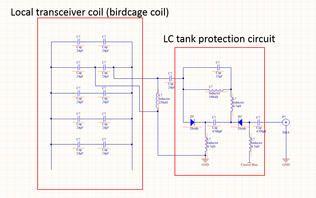
Fig
1. The schematic for the proposed circuit. Two circuits are employed on I/Q
channels of the birdcage coil each other.
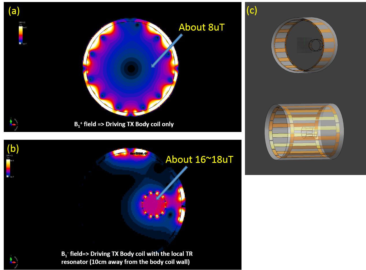
Fig 2. (a) B1+
field generated by TX body coil only, (b) B1- field induced in the local TR resonator,
(c) Setup for two coils for simulation. The local coil was located at 10cm away
from TX body coil on the isocenter.
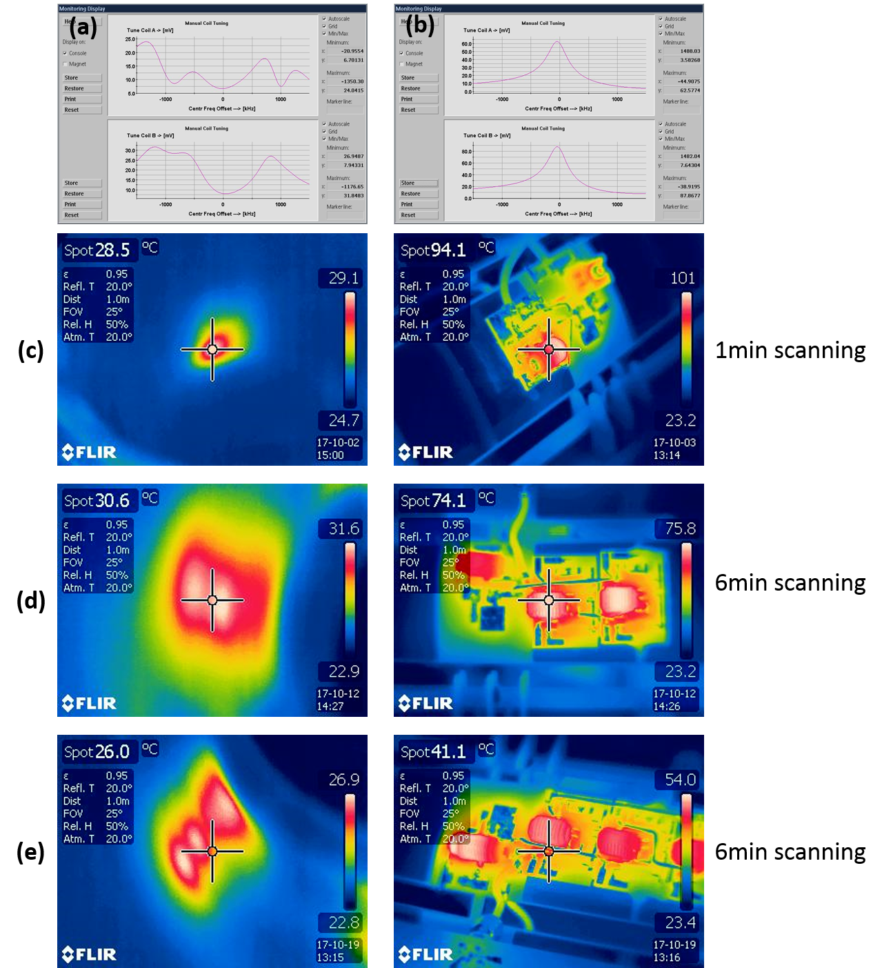
Fig
3. (a)
TX body coil tuning with QLE not implemented LC circuit, (b) TX body coil tuning with QLE
implemented LC
circuit. Temperature measurements on the coil housing and components according
to number of LC protection circuits implemented on QLE transceiver coil. (c)
Single LC, (d) Dual LC, (d) Triple LC.