1458
Transmit Coil impedance measurements to estimate radiofrequency induced currents on wires in MRI1Medical Biophysics, University of Toronto, Toronto, ON, Canada, 2Sunnybrook Research Institute, Toronto, ON, Canada, 3Electrical Engineering Department, Stanford University, Stanford, CA, United States
Synopsis
MRI introduces a safety risk when performing imaged guided interventions caused by induced currents on interventional devices that potentially lead to dangerous temperature increases near their tip. This safety issue can be reduced using parallel RF transmission approaches, although it is difficult to ensure safety when device motion is involved. In this work, impedance changes of a transmit coil are used to estimate the coil’s induced current on a device, and this is extended to a two coil array to determine individual transmit signals needed to reduce the total induced current on a device with simple device geometry.
Introduction
MRI can provide images with information relevant to the success of image guided cardiac interventions, such as RF ablations to
treat ventricular tachycardia1. However, use of MRI introduces a potential safety issue from the RF field inducing a current on the device that
can lead to dangerous temperature increases near the tip2. Parallel RF transmission can reduce this effect by creating a region near the device
where currents induced by transmission from individual coils cancel each other, reducing the heating effect 3. However, cardiac interventions
require the device to change positions which can alter the balance between the induced currents, and potentially still lead to heating. Without a
way to detect the changes device displacement has on the amount of induced current, it would be difficult to ensure safety. Throughout the
procedure an estimate of coupling between the device and individual transmit coils could be useful in detecting if the wire motion alters coupling
to create a potentially hazardous situation. This could also provide information on how to readjust the transmit field to a safe configuration,
previously investigated by Ellenor et. al4. Introduction
Methods
Methods
To study the ability to predict current induction on a wire from coil impedance measurements, a wire was moved in the vicinity of a coil, and induced current and coil impedances were measured. A coupling coefficient is estimated between transmit coil and wire by measuring how much the impedance of the coil changes due to the wire, using a modified version of the reflection coefficient:
$$\Gamma =\frac{\normalsize{Z}\scriptsize{c}-\normalsize{Z}\scriptsize{u}}{\normalsize{Z}\scriptsize{c}+\normalsize{Z}\scriptsize{u}}$$
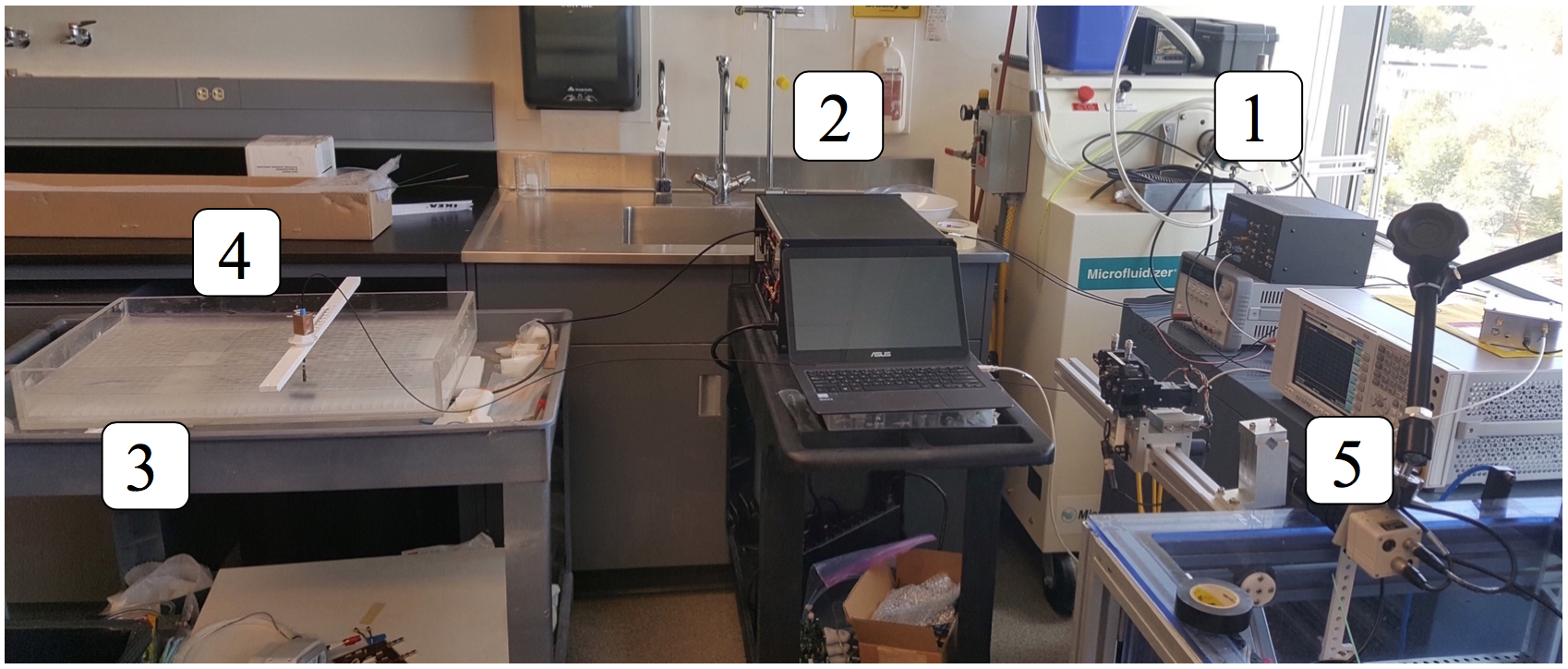
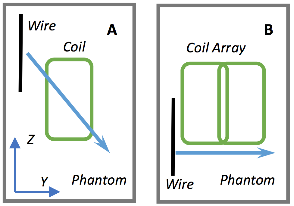
where $$$\normalsize{Z}\scriptsize{c}$$$ is the coil impedance with a coupled device, and $$$\normalsize{Z}\scriptsize{u}$$$ the coil impedance with no device. A 17x12cm rectangular loop coil was built with copper tape, and tuned to have an $$$\normalsize{S}\scriptsize{11}$$$ value of -33.3 dB. The coil was centered 2.5cm below a body mimicking, 9x42x65 cm phantom containing Poly-Acrylic Acid. A 26cm length (approximately the half wavelength at 1.5T) of guidewire (Radifocus Glidewire, Tokyo, Japan) was submerged in the phantom, and moved in 1 cm increments across the coil (relative to coil center, fig 2A). At each location, the coil transmits a series of RF pulses, produced via the Medusa console5 and amplified by a 500W RF amplifier (Procyon Engineering). The peak induced current on the wire is measured with an optical current sensor6. The impedances of the coil were measured using a Network Analyzer. Simulations using FEKO (Altair, MI, USA) were compared with measurements. A second set of simulations were run to calculate a reflection coefficient for each coil in a 2 coil array interacting with a wire (fig 2B). The reflection coefficients were calculated for each coil when only transmitting on that coil as the wire is moved horizontally across the array. The reflection coefficients are used to estimate transmit signal magnitudes and phases $$$\normalsize{(M}\scriptsize{n},\normalsize{\phi}\scriptsize{n}\normalsize{)}$$$ to suppress the peak current at the various wire positions. The values $$$\normalsize{(M}\scriptsize{n},\normalsize{\phi}\scriptsize{n}\normalsize{)}$$$ were calculated for each coil by solving the problem $$$\normalsize\min\scriptsize{M\scriptsize{n},\phi\scriptsize{n},}\normalsize(RW)$$$, $$$\max\sum M\scriptsize{n}$$$ where R is the row matrix of reflection coefficients, and W is column vector of transmit signals $$$\normalsize{(M}\scriptsize{n},\normalsize{\phi}\scriptsize{n}\normalsize{)}$$$ for the 2 coils. The problem was constrained to maximize the sum of transmit magnitudes. The coils were driven with equal transmit signals on both coils and with the transmit signals to reduce current at Y=-10 cm while measuring the peak current for each wire position. The current values were compared to see the effectiveness of the method.
Results & Discussion
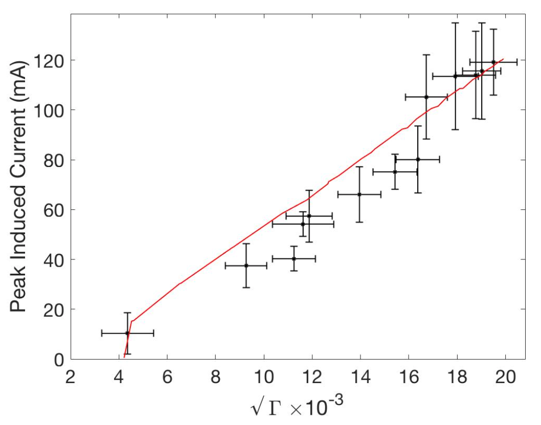
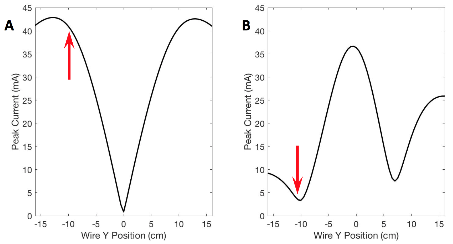
When fitting a model to predict peak induced current from the reflection coefficient, it was noticed taking the square root of the magnitude of the reflection coefficient, resulted in a strongly predictive linear relationship between reflection coefficient and current (figure 3). This relationship was unexpected, and incorporated into the methods of the second set of simulations. Figure 4 shows the peak induced current on the device for the case of equal transmit signals on both coils and with the transmit signals to reduce current at Y=-10 cm. The current was reduced to 3.4 mA from 41 mA. A better optimized solution will be to consider B1 homogeneity in the region of interest, and constrain the problem by the $$$\normalsize\min\scriptsize{M\scriptsize{n},\phi\scriptsize{n},}\normalsize(RW)$$$ term.Conclusions
A fast method to estimate a coupling coefficient between transmit coils and a wire is presented. This is important for cardiac interventions to dynamically adjust the RF field to keep RF induced currents on interventional devices within a safe range. Future work involves a higher coil count, more realistic device positions, and adding a B1 homogeneity term in the optimization.Acknowledgements
Drs. Christine Demore, Simon Graham, and Pascal Stang.
Fred Tam for the use of his server to run the FEKO simulations.
References
1. Halperin HR, Kolandaivelu A. MRI-Guided Electrophysiology Intervention. RMMJ 2010;1(2):e0015.
2. Mattei E, Triventi M, Calcagnini G, et al. Complexity of MRI induced heating on metallic leads: Experimental measurements of 374 configurations. BioMedical Engineering OnLine 2008, 7:11.
3. Etezadi-Amoli M, Stang P, Kerr A, Pauly J, Scott G. Controlling Radiofrequency-Induced Currents in Guidewires Using Parallel Transmit. Magnetic Resonance in Medicine 2015;74:1790–1802.
4. Ellenor C, Stang P, Etezadi-Amoli M, Pauly J, Scott G. Offline Impedance Measurements for Detection and Mitigation of Dangerous Implant Interactions: An RF Safety Prescreen. Magnetic Resonance in Medicine 2015;73:1328–1339.
5. Stang P, Conolly S, Santos J, Pauly J, Scott G. Medusa: A Scalable MR Console Using USB. IEEE Trans Med Imaging. 2012 February; 31(2): 370–379.
6. Zanchi M, Venook R, Pauly J, Scott G. An Optically Coupled System for Quantitative Monitoring of MRI-Induced RF Currents Into Long Conductors. IEEE Trans Med Imaging. 2010 January; 29(1): 169-178.
Figures