1457
Safety of MRI scans of partially implanted entirely insulated conducting wire with spine matrix coil at 3T1Imaging Institute, Cleveland Clnic, Cleveland, OH, United States, 2Radiology, Cleveland Clinic Lerner College of Medicine, Cleveland, OH, United States, 3Physics, Case Western Reserve University, Cleveland, OH, United States
Synopsis
RF-induced heating of an entirely insulated partially implanted conducting wire in a gel phantom was measured at two different 3 tesla systems with a receive-only spine matrix coil. Presence of inner spiral-wound stainless steel helix in Arrow AK-05502 intrathecal catheters raises concern about possible RF-induced heating during MRI. Temperature of the catheter was measured by using fiber optic sensors with fluoroptic monitoring with the catheter inserted into an ASTM gel phantom. Different configurations representing in vivo settings were tested at different E-fields in the phantom. No significant heating was observed in any of the configurations.
Introduction
RF-induced heating of an entirely insulated partially implanted conducting wire in a gel phantom was measured at two different 3 tesla systems with a receive-only spine matrix coil. An Arrow AK-05502 intrathecal catheter (Teleflex, Morrisville, NC), used as sturdy subarachnoid cerebrospinal fluid drains placed for prophylaxis against spinal cord ischemia during aortic aneurysm repair and having inner spiral-wound stainless helix, was used as insulated conducting wire. Temperature changes during routine lumbar spine scans at different points corresponding to different electric (E) fields along the catheter located were measured in this study.Methods
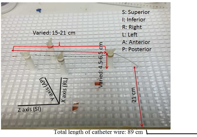
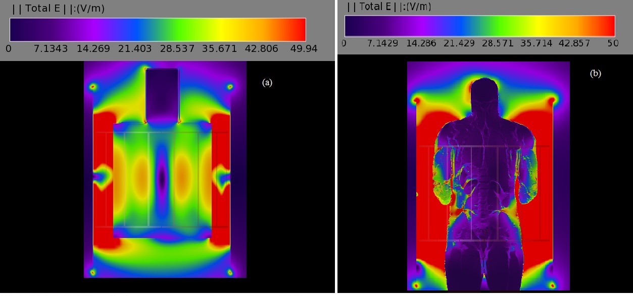
MR scans were performed using 3T Siemens whole body Prisma and Skyra scanners (Erlangen, Germany) with a receive-only spine matrix coil. The 89 cm long catheter was inserted from the back of a polyacrylic gel filled phantom,1 and was guided into the phantom (Fig. 1) closely matching the path followed in human. Inside the phantom, the length traversed along the Z axis (SI direction) was varied between 15 and 21 cm, and the depth from the back/posterior side (AP direction) of the phantom was varied between 4.5 and 6.5 cm. These variations represented different lengths of the catheter inside and outside the dielectric medium, and were made to closely mimic possible scenarios during a human scan. The catheter was run parallel to the Z-axis outside the phantom, as would be in vivo. Two fluoroptic temperature sensors (model m3300, LumaSense Technologies, Santa Clara, CA, USA) were used for temperature measurement. The points of contact of the probes were the insulating tube surrounding the wire (i) close to the tip, at the distal end of the catheter, and (ii) either at a point on the catheter far away from the tip (proximal) or dangling in the gel as a reference. The E-field distribution in the body transmit coil with the gel as dielectric media was simulated (Fig. 2(a)) using commercial software (XFdtd 7.4; Remcom Inc., State College, PA, USA) to solve Maxwell’s equations using the finite-difference time-domain method.2 The RF transmit coil was modeled as a 16-rung high-pass quadrature birdcage coil with a radius of 35.5 cm and a length of 71 cm. The properties of the dielectric medium in the simulation were as follows: dielectric constant = 79 and electrical conductivity = 0.47 S/m. These values are close to the properties of tissues represented by the gel phantom. The points of thermal probe contact on the catheter corresponded to E-fields in the range of ~7-21 V/m, which was smaller than that obtained with simulation of 2 mm Varipose man human model (Fig. 2(b)), ensuring smaller temperature (varies as E2) rise during in vivo scanning. A routine lumbar MRI protocol consisting of the following scans was performed: (i) localizer, (ii) sagittal and coronal Half-Fourier Acquisition Single-shot Turbo spin-Echo (HASTE) localizer (TR/TE/FA=1080ms/97ms/1800, turbo factor (tf)=256), (iii) sagittal T2 weighted Turbo Spin Echo (TSE) (TR/TE/FA=3860ms/85ms/1600, tf=17), (iv) sagittal T1 weighted TSE (TR/TE/FA=600ms/10ms/1600, tf=3), (v) sagittal Short Tau Inversion Recovery (STIR) (TR/TE/TI/FA=7000ms/83ms/180ms/1200, tf=11) and (vi) sagittal T2 weighted TSE (TR/TE/FA=4000ms/108ms/1600, tf=21) (only Prisma scan parameters are listed here). All scans were run only for the combination of 17 cm inside length along Z axis and 5.5 cm distance from the back setting (17/5.5), and then the highest SAR sequence, HASTE, was performed with other length combinations.Results and Discussion
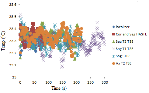
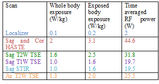
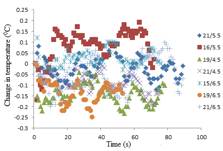
For the sake of brevity only data acquired at the Prisma scanner are presented here. Specific absorption rate (SAR) values recorded for each scan from the console are shown in Table 1. Temperature recordings during all scans with the 17/5.5 setting (described above) did not show any significant (>2oC) heating (Fig. 3). No significant temperature change was observed when the highest SAR sequence (HASTE) was run with the other combination of lengths along Z axis and distance from the back of the phantom (Fig. 4).Testing different combinations of wire lengths inside the phantom at both Prisma and Skyra ensured measurements relevant to safety of patients of different sizes. This testing opens up opportunity for use of this sturdier and conditionally MR safe catheter for subarachnoid draining and post-operative spine MRI. These results do not necessarily generalize and individual centers should perform experiments or simulations to validate safety of performing MR scans in the presence of any such partially implanted insulated conducting wires.Conclusion
Partially implanted fully insulated conducting wires such as Arrow AK-05502 intrathecal catheters do not heat up during spine MRI at 3T Prisma and Skyra scanners with a receive-only spine matrix coil.Acknowledgements
No acknowledgement found.References
1. Baker KB, Tkach JA, Phillips MD, Rezai AR. Variability in RF-induced heating of a deep brain stimulation implant across MR systems. J Magn Reson Imaging. 2006;24(6):1236-1242.
2. Taflove A, Hagness SC. Computational electrodynamics: the finite-difference time-domain method. Norwood, MA: Artech Hhouse; 2005.
Figures