1456
RF-induced heating of a conducting wire entering into a dielectric medium along right-left axis on the presence of another wire during MRI1Imaging Institute, Cleveland Clnic, Cleveland, OH, United States, 2Radiology, Cleveland Clinic Lerner College of Medicine, Cleveland, OH, United States, 3Physics, Case Western Reserve University, Cleveland, OH, United States
Synopsis
RF-induced heating of stereo encephalography (SEEG) electrodes during MRI scans could be of concern. The change in heating pattern of an electrode in the presence of another electrode was investigated by measuring the heating at the tip of a conducting and insulated (bare at tip) wire parallel to B0-field and entering a poly-acrylic gel phantom along left-right axis in the presence of another wire. While the resonance length for maximum heating of the wires did not depend on the number of wires, the temperature rise at the wire tips depended on the relative lengths (resonance / anti-resonance) of the wires.
Introduction
Simultaneous functional MRI (fMRI) and stereo electroencephalography (SEEG) improve identification of epileptogenic zone (EZ), for subsequent resection as a cure for medically refractory focal epilepsy.1 RF induced heating of SEEG electrodes during MRI scans in dielectric media similar to cerebral tissues have been investigated.2,3 Certain resonating lengths can cause excessive heating at the tip of a guidewire.4,5 In order to study heating during MRI with multielectrode SEEG, it is pertinent to understand the effect of coupling of more than 1 electrode. In this study we explored the heating at the tip of a conducting and insulated wire (bare at tip) parallel to B0 field and entering a poly-acrylic gel phantom along left-right (X) axis in the presence of another wire.Methods
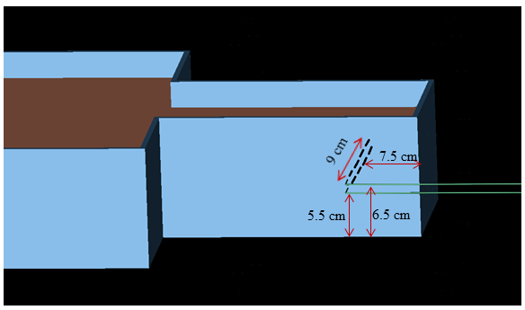
Experiments were performed in a whole body 3T Prisma scanner (Siemens Erlangen, Germany) with a transmit-receive head coil. Heating of single as well as 2 copper wires (each 0.7 mm diameter) during a turbo spin echo (TSE) scan (TR: 6470 ms; TE: 71 ms; Flip angle: 1800; Turbo factor: 15; Echo trains per slice: 18) were studied. The specific absorption rate of the sequence generating 8.3 W of time averaged RF power were whole body: 0.2 W/kg, exposed body: 2.8 W/kg, head: 2.8 W.kg. The wires had polyvinyl chloride insulation throughout the length, except for 2 mm at the tip (as in the tip of a real electrode). An ASTM torso phantom was filled up with polyacryclic gel6 having similar conductivity and dielectric constant as human tissue. Experiments were carried out with (i) a single wire entering the phantom along the X-axis with the wire bent and entering from the side of the phantom with 9 cm of its length in the phantom, and (ii) a 2nd wire entering the phantom similarly but at 1 cm above the 1st wire (Fig. 1). The lengths of the wires were changed by cutting the portion of the outside end while keeping the inside portion lengths fixed at 9 cm (similar to where midline would be in in vivo scan). Temperature changes were measured using fluoroptic temperature sensor (model m3300, Luxtron (Lumasense Technologies), Santa Clara, CA, USA). The system was cooled down to baseline temperature by allowing sufficient time between subsequent measurements For each configuration, the induced RF fields were calculated using finite-difference time-domain (FDTD) method7 based software (XFdtd 7.4; Remcom Inc., State College, PA, USA), followed by thermal simulations to calculate the temperature rise using the same software. The RF transmit coil was modeled as 16-rung high-pass quadrature birdcage coil with 17.5 cm radius, 33 cm length and tuned to 127.6 MHz.Results and Discussion
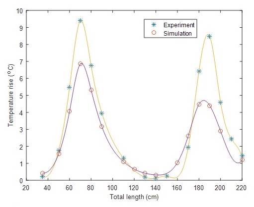
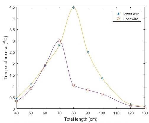
The temperature rise (from experiment and simulation) with a single wire of different lengths is shown in Fig. 2. The 1st two resonances in both cases, were at total lengths of 70 cm and 185 cm (separated by half the wavelength of electromagnetic wave in air at 3T). The experimental and simulation-generated temperature rise of the wire tips during the TSE scan as a function of lengths for 2 wires entering the phantom laterally are shown in Fig. 3 and Fig. 4 respectively. The TSE sequence, not used in vivo, is used here to generate high power (~4-5 times higher than echoplanar imaging for fMRI). The results show that presence of the 2nd wire causes less temperature rise than that with a single wire. While the 1st resonance length of the 1st wire remained the same (~70 cm), that of the 2nd (upper) wire was ~10 cm higher. However, the temperature rise in the lower wire is lower in the experiment, while it is higher is simulation. Also, with 70 cm (resonance length) lower wire and 120 cm (close to anti-resonance length) upper wire combination, the temperature rise of the 2 wires were 11.2oC and 5.8oC respectively. While the simulated and experimental resonance lengths agree with each other, temperature rises differ between experiment and simulation, which may be because of some differences in the properties of the coils (exact geometry etc.) and the gel (dielectric property etc.) used in the 2 cases. This study suggests that coupling of E-fields close to each electrode effectively results in less temperature rise when the lengths of both wires are same. However, combination of resonance and anti-resonance lengths can lead to higher temperature rise in the wire at resonance length.Conclusion
RF-induced heating of 2 wires parallel to B0 and entering dielectric media along X-axis, depend on the relative lengths (resonance / anti-resonance) of the 2 wires.Acknowledgements
Cleveland Clinic Epilepsy Center.References
1. Gonzalez-Martinez J, Bulacio J, Alexopoulos A, Jehi L, Bingaman W, Najm I. Stereoelectroencephalography in the "difficult to localize" refractory focal epilepsy: Early experience from a North American Epilepsy Center. Epilepsia.
2. Bhattacharyya PK, Mullin J, Lee BS, Gonzalez-Martinez JA, Jones SE. Safety of externally stimulated intracranial electrodes during functional MRI at 1.5T. Magn Reson Imaging. 2017;38:182-188. 3. Carmichael DW, Thornton JS, Rodionov R, et al. Feasibility of simultaneous intracranial EEG-fMRI in humans: a safety study. Neuroimage. 2010;49(1):379-390.
4. Armenean C, Perrin E, Armenean M, Beuf O, Pilleul F, Saint-Jalmes H. RF-induced temperature elevation along metallic wires in clinical magnetic resonance imaging: influence of diameter and length. Magn Reson Med. 2004;52(5):1200-1206.
5. Yeung CJ, Karmarkar P, McVeigh ER. Minimizing RF heating of conducting wires in MRI. Magn Reson Med. 2007;58(5):1028-1034.
6. Baker KB, Tkach JA, Phillips MD, Rezai AR. Variability in RF-induced heating of a deep brain stimulation implant across MR systems. J Magn Reson Imaging. 2006;24(6):1236-1242.
7. Taflove A, Hagness SC. Computational electrodynamics: the finite-difference time-domain method. Norwood, MA: Artech Hhouse; 2005.
Figures