1454
Analysis and Design of Lead Wires with Metallic Shielding for Reduction of RF Heating during MRI for Active Implants1Purdue University, West Lafayette, IN, United States
Synopsis
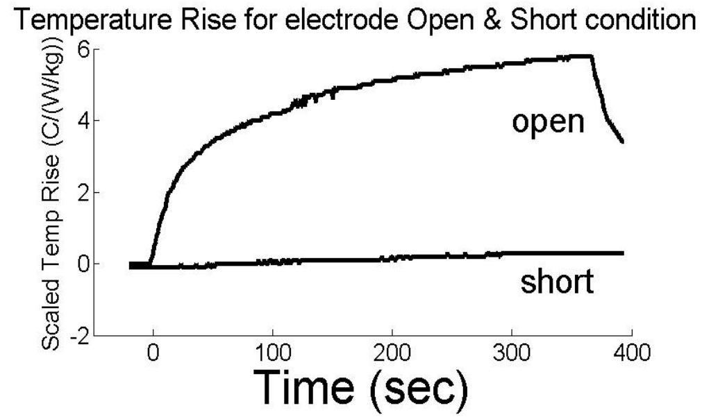
The purpose of this work is to provide a quantitative understanding of how a conducting metallic shield over a lead will reduce RF heating at the electrode during MRI scans. A physical model and equations for reduction of RF heating by a shielded lead are presented. Temperature rise were calculated for different lengths of shielded and unshielded leads. Confirming measurements were made for a quarter wavelength coaxial cable model of the lead. Measured temperature rise and transfer function depended on terminations conditions, with the open lead exhibiting a temperature rise approximately 10 times greater than the shorted lead.
Motivation and Purpose:
The temperature rise at the electrodes of an implanted neurostimulator during MRI scans must be less than the threshold of approximately 6 oC to prevent tissue damage.1 Shielded leads have been developed as a method to reduce RF induced temperature rise at the electrodes.2,3 The purpose of this work is to provide a quantitative understanding of how a conducting metallic shield over a lead, will reduce RF heating at the electrode during MRI scans. The availability of lead wires with reduced heating will allow expanded access to MRI by patients.
Physical description for reduction of RF induced heating by shielding a lead wire:
Figure
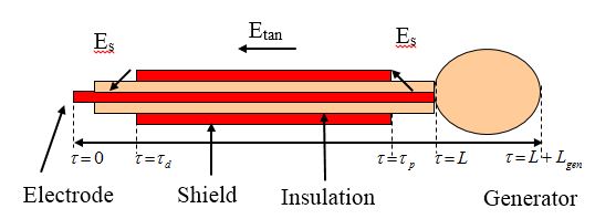
1 shows a representation of an implanted electrical stimulation system with a
generator and a lead wire with an electrode. The background electric field will
induce currents and electric charge on the shield. These will produce a
scattered electric field Es at the edges of the shield. The
tangential component of the scattered field will induce propagating currents on the central
conductor. The current
that is transmitted from the electrode will induce power in the surrounding
tissue.
Let $$$\tau$$$ represent parametric
distance along the lead and let $$$\tau=0$$$ at the distal end of
the electrode, $$$\tau=\tau_{d}$$$ at the distal end of the shield, $$$\tau=\tau_{p}$$$ at the proximal end of the shield, and $$$\tau=L$$$ where the lead enters the
generator. With the shield, the temperature rise $$$\triangle T_{shield}$$$ at electrode is
$$\triangle T_{shield}=|\int_{0}^{\tau_d}S_E^s(\tau)E_{tan}(\tau)d{\tau}+\int_{\tau_p}^{L}S_E^s(\tau)E_{tan}(\tau)d{\tau}+S_E^s(L)\triangle{V_{gen}} |^{2}............................(1)$$
where $$$S_E^s$$$ is the electric field transfer function for the shielded
lead, and $$$\triangle V_{gen}$$$ is an effective
voltage that is developed across the generator due to the background tangential
electric field. We expect that the magnitude of $$$\triangle V_{gen}$$$ to be about $$$|E_{tan}|L_{gen}/2$$$ where Etan is the background electric field at the location of the
generator and is the length of the generator.
Equation
(1) is integrated along the portion of the lead outside the shield
as Etan is zero under the shield. In the absence of the shield, the
temperature rise is
$$\triangle T_{noshield}=|\int_{0}^{L}S_E^b(\tau)E_{tan}(\tau)d{\tau}+S_E^b(L)\triangle{V_{gen}} |^{2}$$ where $$$S_E^b$$$ is the electrode
transfer function without the shield.
Methods for Calculations and Measurements in Phantom
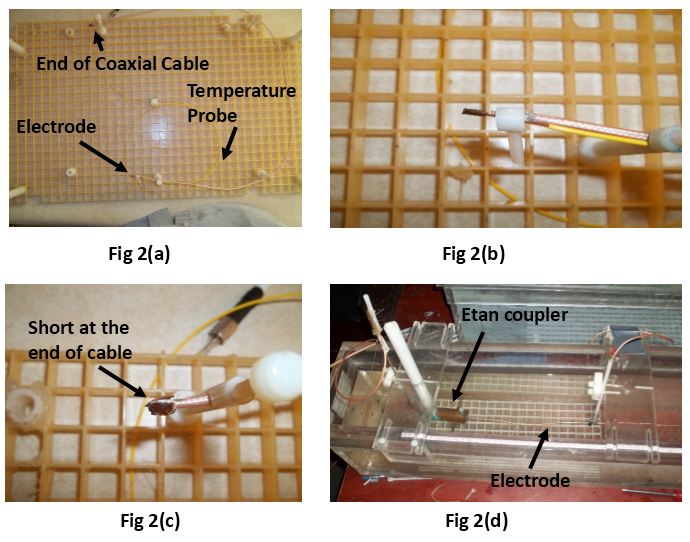
To quantitatively test the model, temperature rise for shielded and unshielded model leads were calculated with FDTD method and measured (Figure 2) in an ASTM rectangular phantom. The model lead is quarter wave length coaxial cable RG 316. An Electrode was formed by removing 6 mm insulation from distal end and proximal end is either shorted or open.The phantom was placed in a GE Signa 1.5T coil and RF power averaging about 3 W/kg over the entire phantom was applied CW. Local SAR at the location of the wire during the tests was 7.1 W/kg. In the simulation, a plane-wave electric field with polarization parallel to the length of the model was applied.
Figure 2(d) illustrates the measurement of transfer function parameter, SE. A tangential electric field is applied over a short length of the lead with a Etan coupler which is translated along the length of the model lead.4 The scattered electric field at the end of the electrode is proportional to the voltage measured with a sensor.
Results of Calculations and Measurements:
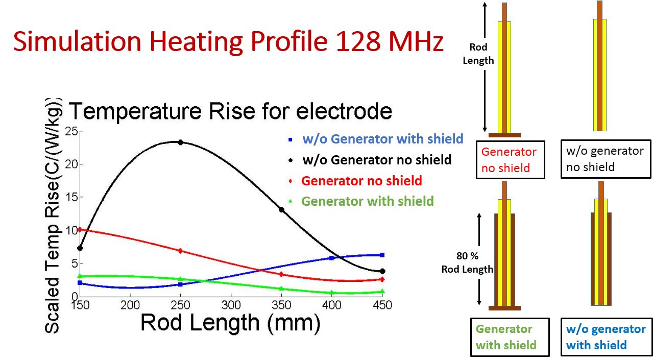
Figure 3 shows the calculated temperature rises vs. lead length at 128 MHz for different configurations of lead. Lowest rises occur for the shielded leads with generator.
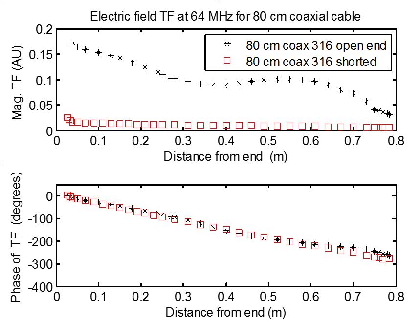
Figure 4 shows the measured electric field transfer function $$$S_E^b$$$ plot for 80 cm shielded lead at 64 MHz. Magnitude of transfer function along the shield is less for the shorted lead as compared to open lead.
Figure 5 shows the measured scaled temperature rises vs. time for open and short condition for 80 cm shielded lead at 64 MHz. The greatest temperature rise occurs for the open-ended cable.
Conclusions
The temperature rise at the electrode with shield $$$\triangle T_{shield}$$$ will differ from the temperature rise for the unshielded $$$\triangle T_{noshield}$$$ for the following reasons.
1) The tangential electric field under the shield will be minimal whereas tangential electric field is equal to the background value for the unshielded lead.
2)The tangential component of the scattered electric field at the edges of the shield will be different, and likely larger in magnitude, compared to background Etan.
3) The electric field transfer function $$$S_E^s$$$ with the shield will differ from the electric field transfer function $$$S_E^b$$$ without shield. This is because the effective wavelength and damping factors for current waves on the lead are different when the insulation is surrounded by body tissues compared to when it is surrounded by the metal shield.
A strategy to minimize temperature rise might involve placing the edges of the shield at locations where $$$S_E^b$$$ is smallest.
Acknowledgements
No acknowledgement found.References
1. R.J. Coffey, R. Kalin, J.M. Olsen, Magnetic Resonance Imaging Conditionally Safe Neurostimulation Leads: Investigation of the Maximum Safe Lead Tip Temperature, Neurosurgery, 74, pp. 215-225, 2014.
2. S. McCabe, J. Scott, "A novel Implant Electrode Design Safe in the RF Field of MRI Scanners", IEEE Trans. Microw. theory and Techniques, VOL 65 NO 9, Sep 2017
3. https://professional.medtronic.com/mri/surescan-mri-radiologists/scs/surescan-system/index.htm#.WgNqHFuPK70
4. S-M Park, R. Kamondetdacha, J.A. Nyenhuis, " Calculation of MRI induced heating of an implanted medical lead wire with an electric field transfer function," J. Magn Reson. Imag., vol. 26, no. 5, pp- 1278-1285, 2007
Figures