1131
Slab-Selective Spectral and Spectral-Spatial Prewinding RF Pulses1Biomedical Engineering, University of Michigan, Ann Arbor, MI, United States, 2Electrical Engineering and Computer Science, University of Michigan, Ann Arbor, MI, United States
Synopsis
We introduce a new type of small-tip angle prewinding RF pulse that compensates for spin dephasing attributed to off-resonance and is also slab-selective, which can help limit the volume of coverage. We design purely spectral slab-selective pulses that prewind a limited global off-resonance bandwidth, and spectral-spatial slab-selective pulses that adapt the prewinding bandwidth spatially. We demonstrate these pulse designs in simulation and in experiments using a gel phantom with a distorted field and a volunteer’s brain. Both pulses create sharp slab profiles, while the spectral-spatial pulse outperforms in terms of target magnetization phase.
Introduction
Spectral “prewinding” RF pulses provide spin-echo like re-phasing of spins in gradient echo sequences1. A small-tip angle2 purely spectral prewinding pulse recovered a limited bandwidth of off-resonance for imaging in the small-tip fast recovery sequence (STFR), a steady state sequence with similar contrast to balanced-SSFP3. A spectral-spatial pulse increased the effective prewinding bandwidth by varying the bandwidth spatially using a 2D field map4. Here, we demonstrate for the first time the incorporation of spectral prewinding into slab-selective pulses; these are practically important for limiting the FOV in the slab dimension.Methods
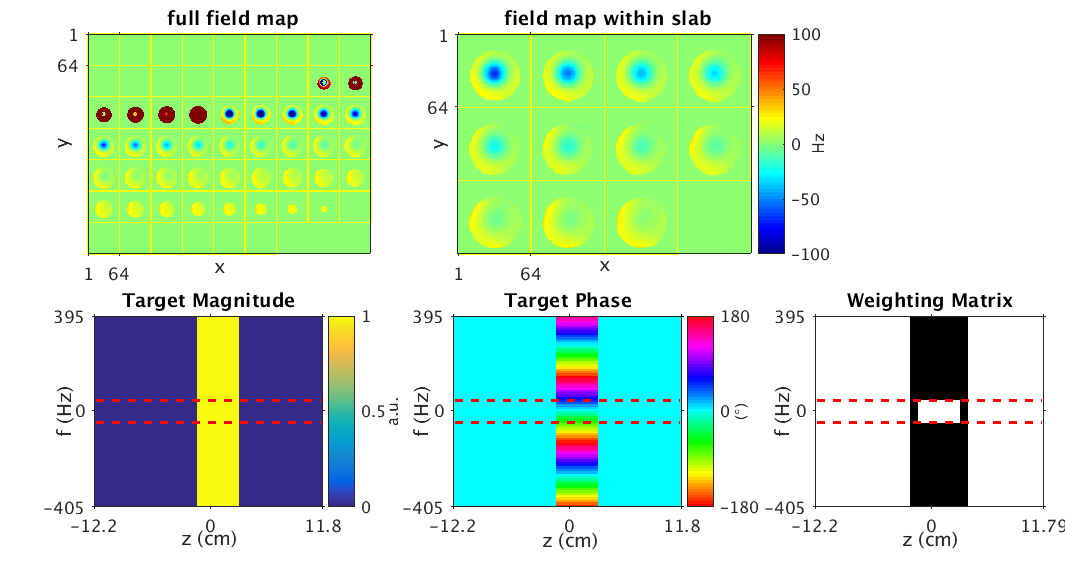
We designed slab-selective prewinding pulses to excite target pattern, $$$\textbf{d}$$$, by sampling the function:
$$d(z,f)=p(z)e^{2\pi i\;\mathrm{TE}\;f}$$
where $$$z$$$ is the slab dimension, $$$f$$$ is a range of off-resonance frequencies within a 3D field map, $$$p(z)$$$ is the slab-select envelope, and echo time $$$\mathrm{TE}$$$ is half the steady-state free precession time for STFR. As written, $$$\textbf{d}$$$ defines the purely spectral3 slab-selective pulse, and we replicate it over transverse dimensions $$$x$$$ and $$$y$$$ to create a 4D spectral-spatial4 slab-selective pulse.
We designed the RF pulses by solving a small-tip angle approximation (STA)2 constrained optimization problem:
$$\hat{\textbf{b}}=\arg\min_{\textbf{b}}\vert\vert\textbf{Ab}-\textbf{d}\vert\vert_{\textbf{W}}^{2}\;\;\mathrm{s.t.}\;\vert\vert\textbf{b}\vert\vert_{\infty}\leq b_\mathrm{max}$$
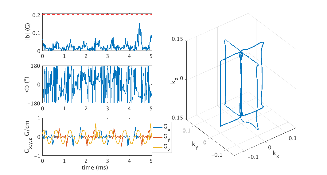
Where $$$\textbf{A}$$$ is the STA system matrix, $$$\textbf{W}$$$ is a weighting matrix, and $$$b_{\mathrm{max}}$$$ is the peak RF amplitude limit (0.2 Gauss). For the purely spectral slab-selective pulse, $$$\textbf{W}$$$ is unity except for the transition regions between in-slab and out-of-slab areas as well as for frequencies outside of the field map within the slab which are allowed to vary freely. For the spectral-spatial version $$$\textbf{W}$$$ is a 4D weighting function, extending ref. (4) to 3D. Figure 1 shows a 3D field map and an example of a 2D spectral target pattern and weighting matrix.
We obtain slab selectivity by applying excitation gradients during the RF pulse that sweep through kz-space. In the spectral-spatial slab-selective pulse, we employ additional x and y gradients that span the transverse excitation k-space as kx-ky blips, making a 3D spokes trajectory. We explored multiple spokes trajectories for the RF designs to balance between spectral and slab selectivity, while still maintaining a short pulse length. We generally found that four spokes at $$$\pm k_{x,\mathrm{max}}$$$ and $$$\pm k_{y,\mathrm{max}}$$$, repeated twice, worked sufficiently well--however spoke selection remains an open area of research.
To mimic realistic field distortions, we attached a small piece of metal to a gel phantom, and then acquired a field map. We then designed 5.04ms spectral and spectral-spatial slab-selective pulses to excite a 4cm slab. For both pulse types, we designed tip-down and tip-up pulses for the STFR sequence, where the tip-up pulse is formed by negating and reversing a pulse designed to excite the simulated magnetization magnitude and phase accrued at the end of free precession5. We used these pulses to acquire STFR images [FA/TE/TR=16°/3.6ms/18.3ms, FOV=24cm/24cm/24cm, matrix size 256x256x60] using a birdcage single channel T/R head coil on a 3T GE MR750 scanner. We repeated this experiment in a volunteer’s brain. The 4D spectral-spatial slab-selective pulses were the most computationally demanding, taking about 3 min to compute online.
Results
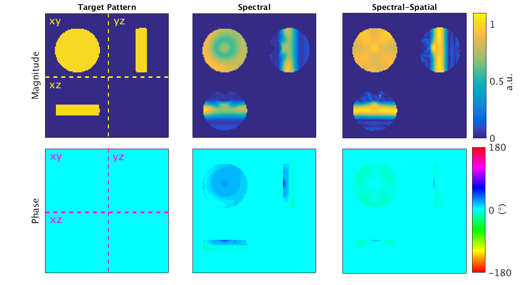
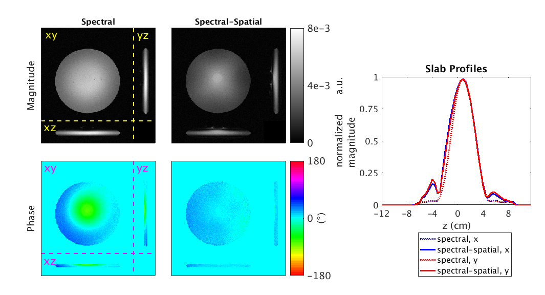
Figure 2 shows the tip-down RF and gradient waveforms and the 3D spokes k-space trajectory for the spectral-spatial pulse used in the phantom. Figure 3 shows the simulated magnetization and phase for the target design pattern and the spectral and spectral-spatial slab-selective pulses in the phantom at TE after a single excitation (i.e., not in steady-state). The simulated full-FOVz magnitude NRMSE and in-slab phase RMSE were 0.31/15.5° and 0.15/2.1° for the spectral and spectral-spatial pulses, respectively. Figure 4 shows the experimental images in the phantom.
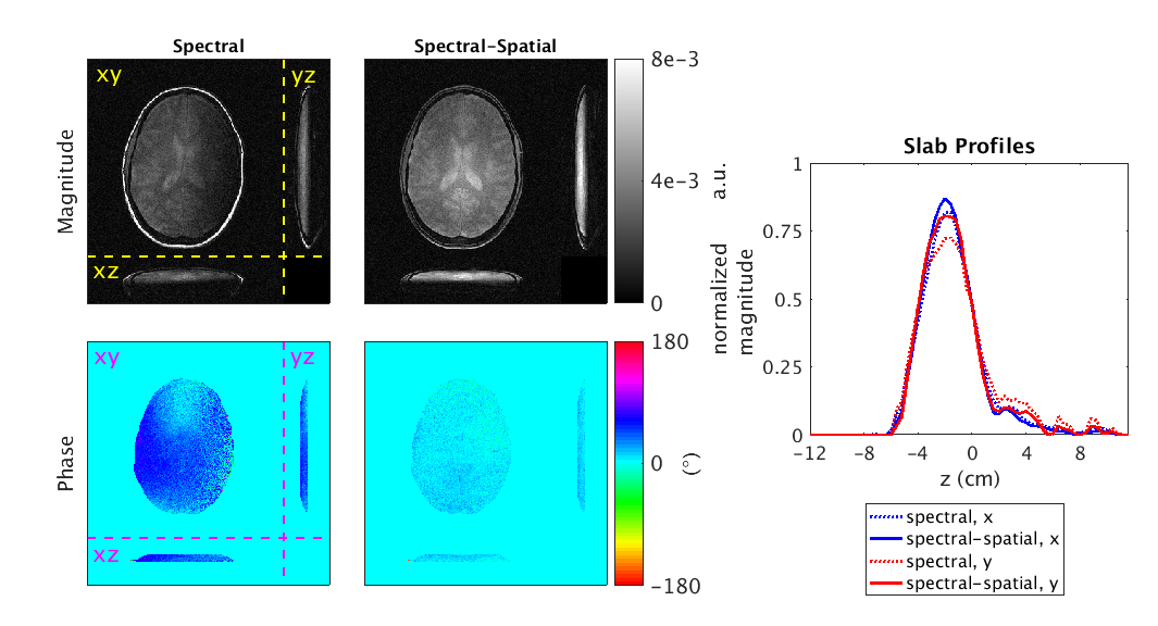
Figure 5 shows the experimental images from the analogous experiment repeated in a volunteer. The magnitude NRMSE and phase RMSE computed from simulated images (not shown) were 0.25/7.2° and 0.12/1.4° for the spectral and spectral-spatial pulses, respectively.
Discussion and Conclusion
Prewinding slab-selective pulses are challenging because there is an inherent trade-off between slab-selectivity and phase prewinding. In simulation, spectral-spatial pulses balanced these competing needs more effectively than purely spectral slab-selective pulses by achieving lower magnitude NRMSE and phase RMSE. The spectral pulse achieved a sharper slab profile in the phantom than the spectral-spatial pulse, but again was outperformed by the spectral-spatial pulse slab profile in the human experiment as well as all phase images (phantom and human). Performance differences between simulation and experiment in the phantom might be attributed to steady-state behavior of the STFR sequence, as the simulation is conducted at TE directly after a single tip-down pulse.
Future work will involve optimizing the 3D excitation trajectory to balance slab-selectivity and spectral prewinding. Additionally, strategies to improve the tip-up pulse design could better match the simulated magnetization with the experimental steady-state results using STFR.
Acknowledgements
This work was supported by NIH Grant R01EB023618.
References
1. Assländer J, Glaser SJ, Hennig J. Spin echoes in the regime of weak dephasing. Magn Res Med 2016;75:150–160.
2. Pauly J, Nishimura D, Macovski A. A k-space analysis of small-tip angle excitation. J Magn Reson 1989;81:43–56.
3. Sun H, Fessler JA, Noll DC, Nielsen JF. Balanced SSFP-like steady-state imaging using small-tip fast recovery (STFR) sequence with a spectral pre-winding pulse. Magn Res Med 2016;75:839–844.
4. Williams SN, Nielsen JF, Fessler JA, Noll DC. Design of spectral-spatial phase prewinding pulses and their use in small-tip fast recovery steady-state imaging. Magn Res Med 2017; DOI 10.1002/mrm.26794.
5. Nielsen JF, Yoon D, Noll DC. Small-tip fast recovery imaging using non-slice-selective tailored tip-up pulses and radiofrequency-spoiling. Magn Res Med 2013;69:657–666.
Figures