1127
On the Point of Gradient Moment Expansion for Multi-Spoke RF Pulses1Medical Physics in Radiology, German Cancer Research Center (DKFZ), Heidelberg, Germany, 2Physikalisch-Technische Bundesanstalt (PTB), Braunschweig and Berlin, Germany
Synopsis
In this work we investigated the influence of the point of gradient moment expansion (texp) for multi-spoke RF pulses. The results demonstrate that texp=tISO is ideal if no flow in the RO direction is present, but severe displacement artifacts occur if this is the case. texp=TE induces shifts that are directed along the vessel orientation and are independent of the encoding orientation. The presented techniques are the basis for correct velocity quantification with controlled displacement for multi-spoke RF pulses allowing in-plane B1+ homogenization using parallel transmission at UHF.
Purpose / Introduction
In Ultra-High-Field MRI spatial flip angle heterogeneities have been successfully addressed using three-dimensional tailored (“multi-spoke”) RF pulses [1-3]. In the presence of flow, however, it was shown that these pulses cannot be applied straightforwardly [4]. Recently, the use of spoke pulses for phase-contrast velocity imaging [5] with flow perpendicular to the slice was demonstrated.
Here we generalize this work towards spoke pulses for 4D flow MRI with arbitrary flow directions. We investigate two different methods of $$$m_1$$$-encoding to control well-known spatial shift artifacts in 4D flow MRI when using spoke pulses. Solutions for 2-spoke excitation are presented and validated in a flow phantom and in-vivo.
Theory
In MR velocimetry, the velocity is encoded through the first moment of bipolar gradients with wavefrom $$$G(t)$$$ that affect the magnetization's phase $$$\phi(r,v)=\gamma{r_0}m_0+\gamma{v}m_1$$$. This results from a Taylor expansion with $$$m_0=\int_{t_0}^{TE}G(t)~dt$$$ and $$$m_1=\int_{t_0}^{TE}G(t)\cdot{t}~dt$$$. $$$t_0$$$ is typically set to the isodelay point ($$$t_{ISO}$$$), which is the RF center for symmetrical RF pulse.
For conventional 4D flow MRI (using standard slice-selective pulses) and single-sided encoding $$$m_1$$$ is typically calculated such that $$$m_1=\frac{\pi}{\gamma{VENC}}$$$. $$$m_0$$$ and $$$m_1$$$ of the two phase encoding (PE) directions are often set to linearly vary $$$m_0$$$ from line to line while $$$m_1$$$ is constant for all lines. In the readout direction (RO), however, $$$m_1$$$ approximates
a linear variation during the data acquisition generating
a velocity-dependent displacement $$$\triangle_{RO}=v\cdot{TE}$$$. For oblique flow, this is critical as the blood signal can shift out of the vessel. Therefore, one can generate the same linear change in $$$m_1$$$ along both PE directions, resulting in shifts along the direction of the blood velocity vector. This solution mathematically corresponds to shifting the expansion time ($$$t_{exp}$$$) of the Taylor expansion from $$$t_{exp}=t_{ISO}$$$ to $$$t_{exp}=TE$$$.
Methods
We converted the two above mentioned methods of I) $$$t_{exp}=t_{ISO}$$$ (no shift in PE direction) and II) $$$t_{exp}=TE$$$ (shift along velocity vector) from 1-spoke to 2-spoke excitation. Note, however, that this solution is applicable to an arbitrary number of spoke pulses.
In the 2-spoke case two isodelay points $$$t_{ISO}^{1}$$$ and $$$t_{ISO}^{2}$$$ exist. To fulfill $$$m_1=\frac{\pi}{\gamma{VENC}}$$$ for all PE lines and both RF pulses (method I) bipolar gradients are included between the spoke pulses on both PE axes as illustrated in Fig. 1a. These gradients are calculated on-line within the sequence.
For method II, no bipolar gradients are needed in the slice direction (second PE axis) and standard rewinder gradients can be used (Fig. 1b).
The 2-spoke 4D-flow sequence was applied at 7T (Siemens Healthcare, Germany) with both methods. A flow phantom as well as the femoral artery of a healthy volunteer was imaged using a 28-channel knee coil (Quality Electrodynamics, USA). In-vivo data
were acquired after obtaining consent to an IRB-approved protocol and cardiac
triggering was used to allow the reconstruction of different cardiac phases. Imaging
parameters for the measurements are listed in Tab. 1. The two-spoke excitation
was used to generate a sinusoidal tagging pattern in order to visualize flow effects.
Results
For $$$t_{exp}=t_{ISO}$$$ (method I) for both pulses, bipolar rewinder gradients are required between the pulses (Fig. 1a). In contrast, standard monopolar gradients fulfill the condition for $$$t_{exp}=TE$$$ (Fig. 1b), which significantly reduces TR by $$$16.0-17.4\%$$$ for the used imaging parameters.
Fig. 2 demonstrates the impact of $$$t_{exp}$$$ for oblique flow. For $$$t_{exp}=t_{ISO}$$$ the image is unaffected if the flow is perpendicular to the RO direction. For non-zero flow components in the RO direction, however, displacement artifacts are observed. In the case of $$$t_{exp}=TE$$$ there is no dependency on the encoding orientation and the flow-induced shifts are only along the vessel orientation, indicated by distorted tagging patterns.
The animated Figures 3-4 show the difference between the two methods for a temporally resolved in-vivo acquisition. In Figure 3 an apparent movement of the popliteal artery in the RO direction can be observed which is greatest in mid-systole. Figure 4, in contrast, shows no shifts oblique to the artery but only a shift along the vessel direction, visualized by the tagging pattern.
Discussion
In this work we investigated the influence of $$$t_{exp}$$$ for multi-spoke RF pulses. The results demonstrate that $$$t_{exp}=t_{ISO}$$$ is ideal if no flow in the RO direction is present, but severe displacement artifacts occur if this is the case. $$$t_{exp}=TE$$$ induces shifts that are directed along the vessel orientation and are independent of the encoding orientation. The presented techniques are the basis for correct velocity quantification with controlled displacement for multi-spoke RF pulses allowing in-plane B1+ homogenization using parallel transmission at UHF.Acknowledgements
No acknowledgement found.References
[1] Saekho, S., Yip, C.-y., Noll, D. C., Boada, F. E. and Stenger, V. A. (2006), Fast-kz three-dimensional tailored radiofrequency pulse for reduced B1 inhomogeneity. Magn Reson Med, 55: 719–724. doi: 10.1002/mrm.20840
[2] Setsompop, K., Alagappan, V., Gagoski, B., Witzel, T., Polimeni, J., Potthast, A., Hebrank, F., Fontius, U., Schmitt, F., Wald, L. L. and Adalsteinsson, E. (2008), Slice-selective RF pulses for in vivo Bmath image inhomogeneity mitigation at 7 tesla using parallel RF excitation with a 16-element coil. Magn. Reson. Med., 60: 1422–1432. doi:10.1002/mrm.21739
[3] Schmitter, S., DelaBarre, L., Wu, X., Greiser, A., Wang, D., Auerbach, E. J., Vaughan, J. T., Uğurbil, K. and Van de Moortele, P.-F. (2013), Cardiac imaging at 7 tesla: Single- and two-spoke radiofrequency pulse design with 16-channel parallel excitation. Magn. Reson. Med., 70: 1210–1219. doi:10.1002/mrm.24935
[4] Schmidt, S., Flassbeck, S., Breithaupt, M., Ladd, M. E., Schmitter, S. (2016), On the Performance of Multi-Spoke RF Pulses in the Presence of Laminar Flow - a Simulation Study. Magn. Reson. Mat. Phys. Biol. Med., 29(1 Supplement), 2016. ESMRMB 2016, 33rd Annual Scientific Meeting, Vienna, AT, September 29 - October 1, contribution no. 381.
[5] Schmidt, S., Flassbeck, S., Breithaupt, M., Ladd, M. E., Schmitter, S. (2017), Velocity Encoded and Compensated Multi-Spoke RF Pulses for Flow Quantification at Ultra-High Fields. In Proceedings of the 25th Annual Meeting of the ISMRM, Honolulu, HI, USA, 2017. Abstract 0389.
Figures
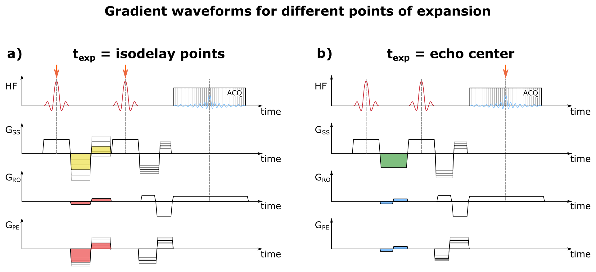
Figure 1:
a) Gradient waveform if the isodelay points are chosen as the point of expansion (red arrows). Between consecutive spoke pulses bipolar gradients (yellow) have to be added to adjust the first gradient moment experienced by each spoke pulse. The blip-moments in RO and PE-direction are applied by the red bipolar gradients. In any phase-encoding direction the gradients have to be adjusted for each encoding step.
b) Gradient waveform if the echo center is chosen as the point of expansion (red arrow). In this case inverted slice-select gradients can be used (green). The blip-moments are applied by the blue bipolar gradients.
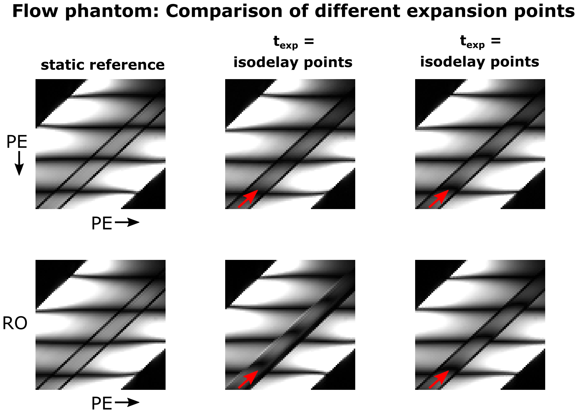
Figure 2:
Slice of a 3D
acquisition with two
spoke excitation to create a sinusoidal tagging pattern. The red arrows indicate the flow direction.
Top/Bottom: RO direction orthogonal/oblique to the flow direction.
Middle: For expansion around the isodelay points of the two spoke pulses shifts can be minimized if no flow is present in the RO direction. However, nonzero flow in the RO direction lead to severe displacement artifacts resulting in the flow signal overlaying stationary tissue.
Right: If the gradient moments are expanded around TE the shifts are along the flow direction and only a distortion of the tagging pattern is observed.
Figure 3 (animated):
Time resolved 2D acquisition of the popliteal artery of a healthy volunteer with corresponding velocity quantification for texp=tISO. Two spoke pulses were used to create a sinusoidal tagging pattern. Oblique flow results in apparent movement of the popliteal artery in the RO direction due to displacement artifacts. The corresponding velocities show distorted patterns at the edge of the vessel where flow signal is overlaying stationary tissue. For the velocity overlay red colors indicate high velocities.
Figure 4 (animated):
For texp=TE the observed shifts are along the vessel (visualized by the tagging pattern) and therefore no apparent movement of the vessel can be seen. Since the flow signal shifts along the vessel no overlay with stationary signal occurs resulting in an undisturbed flow profile across the vessel. For the velocity overlay red colors indicate high velocities.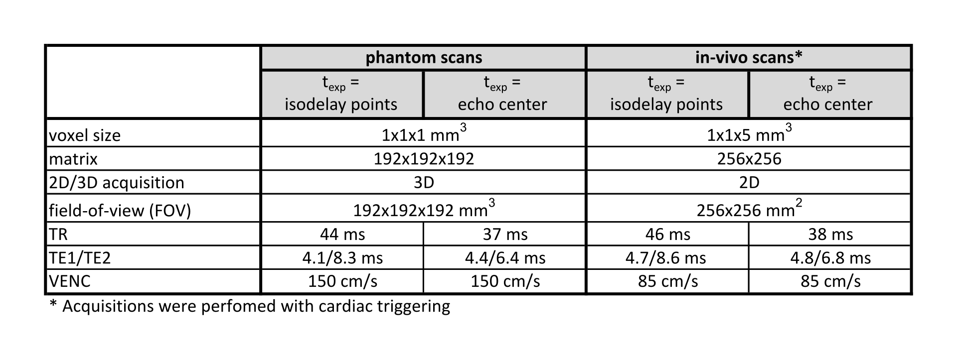
Table 1:
Imaging parameters for both, phantom and in-vivo scans. TE1 and TE2 are the echo times for both spoke pulses. The use of bipolar gradients between consecutive pulses for texp=tISO leads to an increase in TR compared to the monopolar slice rewinders used in the case of texp=TE.