1017
Fast 3D MR fingerprinting with spiral projection acquisition for whole brain quantification imaging1Center for Brain Imaging Science,Department of Biomedical Engineering, Zhejiang University, Hangzhou, China, 2State Key Laboratory of Modern Optical Instrumentation, College of Optical Science and Engineering, Zhejiang University, Hangzhou, China
Synopsis
A spiral projection acquisition scheme was used for 3D MR fingerprinting to achieve isotropic resolution of 1.2x1.2x1.2 mm3 with FOV of 240x240x240 mm3 for whole brain T1 and T2 mapping within 4.3 minutes.
Purpose
To develop a fast three-dimensional (3D) magnetic resonance fingerprinting (MRF) method based on spiral projection acquisition to achieve high resolution isotropic quantitative mapping.Introduction
Magnetic Resonance Fingerprinting (MRF) is a novel quantitative imaging technique to estimate multiple parameters simultaneously 1. To realize 3D MR fingerprinting, stack-of-spiral acquisition scheme has been used in some previous studies 2,3. In this work, an acquisition scheme based on spiral projection 4,5 was proposed for 3D MR fingerprinting to achieve faster quantification imaging for whole brain.Methods
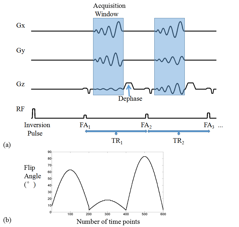
Acquisition trajectories based on spiral projection imaging (SPI) 4,5 was implemented for 3D slab-selective MR fingerprinting with fast imaging with steady state precession (FISP) readout 6. As Figure 1(a) shows, rotating spiral readouts were acquired for 600 time points (TRs) per each group repetition (GR) and 30 group repetitions for whole scan. The spiral trajectory was firstly rotated about z-axis to fully sample a plane like a “disk”. This disk was then rotated about x-axis to fill a sphere in k-space. Since the necessary number of spirals to fill a disk is much less than the necessary number of disks to fill a sphere (30 compared to 200 in this work), spiral rotates 12° about z-axis by group repetitions and about x-axis at golden angle (111.25°) by time points within each group repetition to minimize total acquisition time.
Pulse sequence design was shown in Figure 2a. Varying flip angles were illustrated in Figure 2b while TRs were set as constant value of 11 ms with the number of time points = 600. The number of group repetition was 30 and the identical pulse sequence was used for each group except for rotated acquisition trajectories. The interval between sequential group repetition was 2 seconds. Therefore, the total scan time was 4 minutes and 16 seconds. The isotropic spatial resolution of 1.2x1.2x1.2 mm3 was achieved for the identified parametric maps in a field of view (FOV) of 240x240x240 mm3 and matrix size of 200x200x200. The measurements of a phantom and in vivo brains were performed on a Siemens 3T Prisma scanner with a 64 channel head coil.
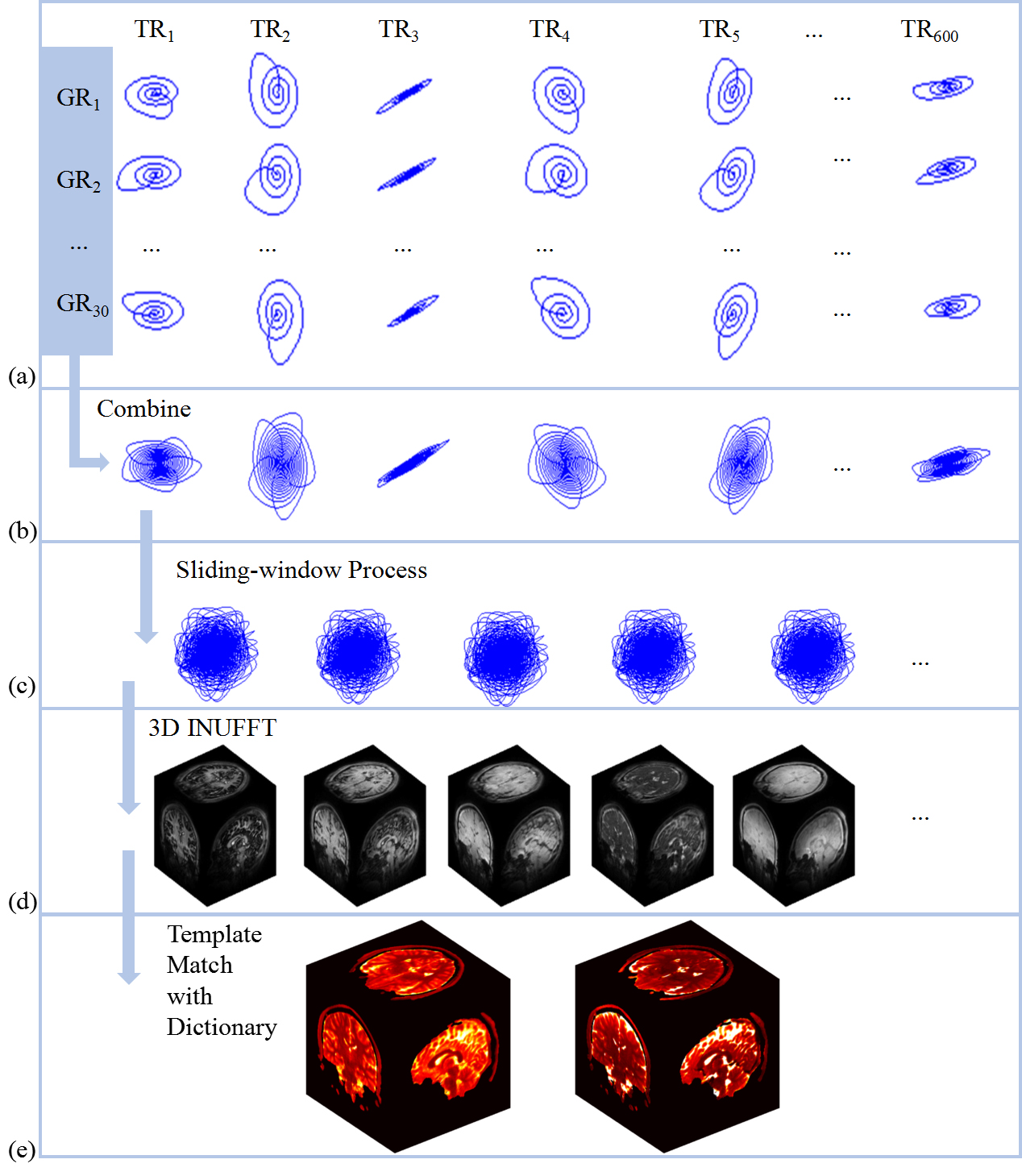
Reconstruction is achieved by following these steps, shown in figure 1. First, acquired spiral interleaves was combined from all group repetitions into a disk-like trajectory at each time point. Second, the inverse NUFFT operator was applied to k-space data with a sliding-window strategy 7. Third, the reconstructed image frames were matched to a sliding-windowed MRF dictionary (calculated by EPG algorithm 8) to generate parametric maps.
Results
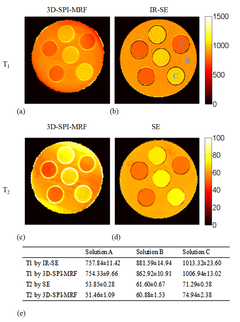
Figure 3 shows the result of a phantom (comprised of three solutions with different concentration of agar and MnCl2) study. The T1 and T2 values obtained by the proposed method (shown in Figure 2e) were close to the ones from the gold standard method (IR-SE for T1 and SE for T2), without bias which often occurs in 2D MRF due to defective slice profile of RF excitation 9.
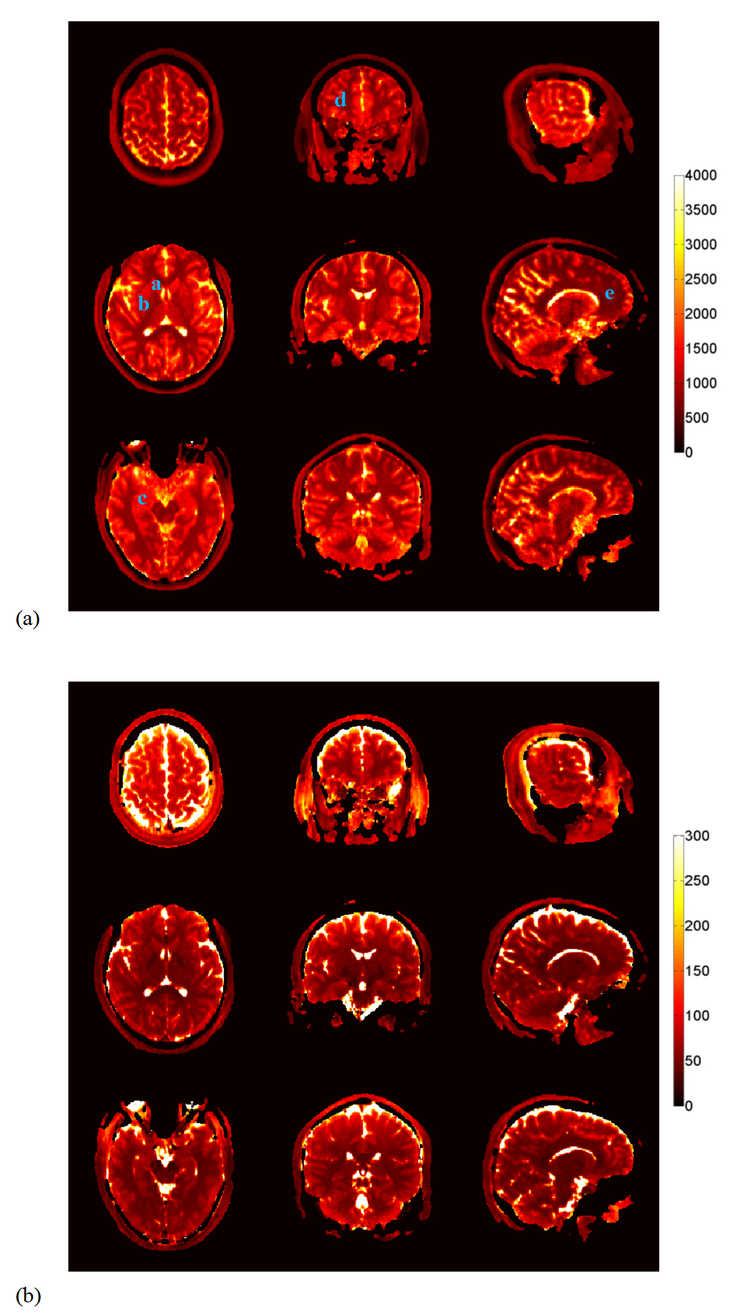
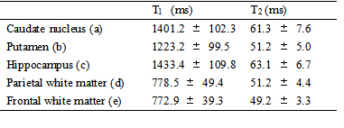
Figure 4 shows the T1 (a) and T2 (b) maps of different slices and different orientations for an in vivo study. Some regions of interest were marked by blue characters, respectively corresponding to the caudate nucleus, putamen, hippocampus, parietal white matter and frontal white matter from a to e. Their specific T1 and T2 values were listed in Table 1.
Discussion and Conclusion
Compared to other acquisition scheme previously used for 3D MRF, such as stack of spiral acquisition, the proposed method adopted spiral projection acquisition to achieve a higher acquisition efficiency. By placing the z-axis rotation of spiral on group repetition dimension and x-axis rotation on time repetition dimension, the number of group repetitions is identical to the number of disks for sphere k-space filling, namely 30 in this work, allowing the proposed method to achieve isotropic resolution of 1.2mm with FOV = 240x240x240mm3 for whole brain scan within 4.3 minutes. Since the reconstruction process is without any iterative calculation, the total reconstruction time is significantly short (about 3 hours without any computation acceleration) compared to 3D MRF methods which adopt iterative algorithm for reconstruction 3. Besides, some relevant researches have demonstrated that the spiral projection acquisition scheme can reduce motion artifacts 4 or be used for motion estimation and correction 5. This is very important for 3D quantification imaging and with many potential applications such as abdomen scans.Acknowledgements
This work was supported by the National Key R&D Program of China (2017YFC0909200), National Natural Science Foundation of China (81401473, 91632109,61701436) and the Fundamental Research Funds for the Central Universities (2017QNA5016).References
1. Ma D, Gulani V, Seiberlich N, Liu K, Sunshine JL, Duerk JL, Griswold MA. Magnetic resonance fingerprinting. Nature 2013;495(7440):187-192.
2. Ma D, Jiang Y, Chen Y, McGivney D, Mehta B, Gulani V, Griswold M. Fast 3D magnetic resonance fingerprinting for a whole-brain coverage. Magnetic resonance in medicine 2017;DOI:10.1002/mrm.26888.
3. Liaoc C, Bilgic B, Manhard M, Zhao B, Cao X, Zhong J, Wald L, Setsompop K. 3D MR fingerprinting with accelerated stack-of-spirals and hybrid sliding-window and GRAPPA reconstruction. NeuroImage 2017;162:13-22.
4. Casets C, Lefrancois W, Wecker D, Ribot E, Trotier A, Thiaudiere E, Franconi J, Miraux S. Fast 3D Ultrashort Echo-Time Spiral Projection Imaging Using Golden-Angle: A Flexible Protocol for In Vivo Mouse Imaging at High Magnetic Field Magnetic resonance in medicine 2017;77:1831-1840.
5. Johnson K, Robison R, Pipe J. Rigid Body Motion Compensation for Spiral Projection Imaging. IEEE transaction on medical imaging 2011;30:655-665.
6. Jiang Y, Ma D, Seiberlich N, Gulani V, Griswold MA. MR fingerprinting using fast imaging with steady state precession (FISP) with spiral readout. Magnetic resonance in medicine 2015;74(6):1621-1631.
7. Cao X, Liao C, Wang Z, Chen Y, Ye H, He H, Zhong J. Robust sliding-window reconstruction for Accelerating the acquisition of MR fingerprinting. Magnetic resonance in medicine 2017;78(4):1579-1588.
8. Weigel M. Extended phase graphs: dephasing, RF pulses, and echoes - pure and simple. Journal of magnetic resonance imaging : JMRI 2015;41(2):266-295.
9. Ma D, Coppo S, Chen Y, McGivney DF, Jiang Y, Pahwa S, Gulani V, Griswold MA. Slice profile and B1 corrections in 2D magnetic resonance fingerprinting. Magnetic resonance in medicine 2017;78(5):1781-1789.
Figures