0947
Direct Generation of MR Images in a Divergent Coordinate System for MRI Radiotherapy Hybrids1Medical Physics, Oncology, University of Alberta, Edmonton, AB, Canada, 2Medical Physics, Cross Cancer Institute, Edmonton, AB, Canada
Synopsis
The direct generation of images in a divergent coordinate system may be important to some applications of MR imaging in MRI-radiotherapy hybrids. Specifically, in the circumstance where 2D images are being used for real-time therapy beam guidance, image generation in a divergent coordinate system that matches that of the treatment beam (which originates from a single source point) will reduce targeting errors and inadvertent dosing of critical structures. This work presents a theoretical hardware solution to a variety of MRI-radiotherapy implementations which involve the replacement or augmentation of conventional linear gradients. An experimental and simulated verification is presented.
Introduction
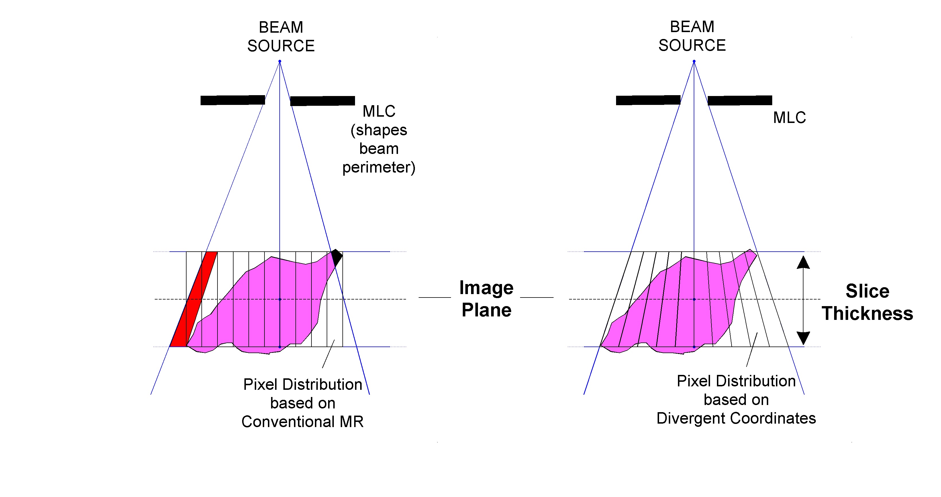
A number of MRI-radiotherapy hybrids have been developed in recent years.1-4 In general the MRI may operate as do conventional units, save for some extra attention to geometric fidelity. However, one of the imaging tasks that these hybridized MRI units will perform is the real-time imaging of target and critical structures to guide or gate the treatment beam. In these circumstances, it is important that the pixels within the guiding images represent unique cross-sections of the treatment beam, which is inherently delivered in a coordinate system that diverges from a single source point. Targeting structures based on a conventional cartesian coordinate system may therefore lead to targeting errors. Figure 1A illustrates this problem, where pixels based on a conventional geometry can lead to overestimation of structure boundaries in some areas, and underestimation in others. Figure 1B illustrates the generation of images based on a divergent geometry (also called images in the Beam's Eye View (BEV)), and how this will result in the elimination of these boundary errors. This work introduces a theoretical description of the hardware modifications that would be required to allow MRI to support this geometry. Verification is provided through experiment and simulation.Theory
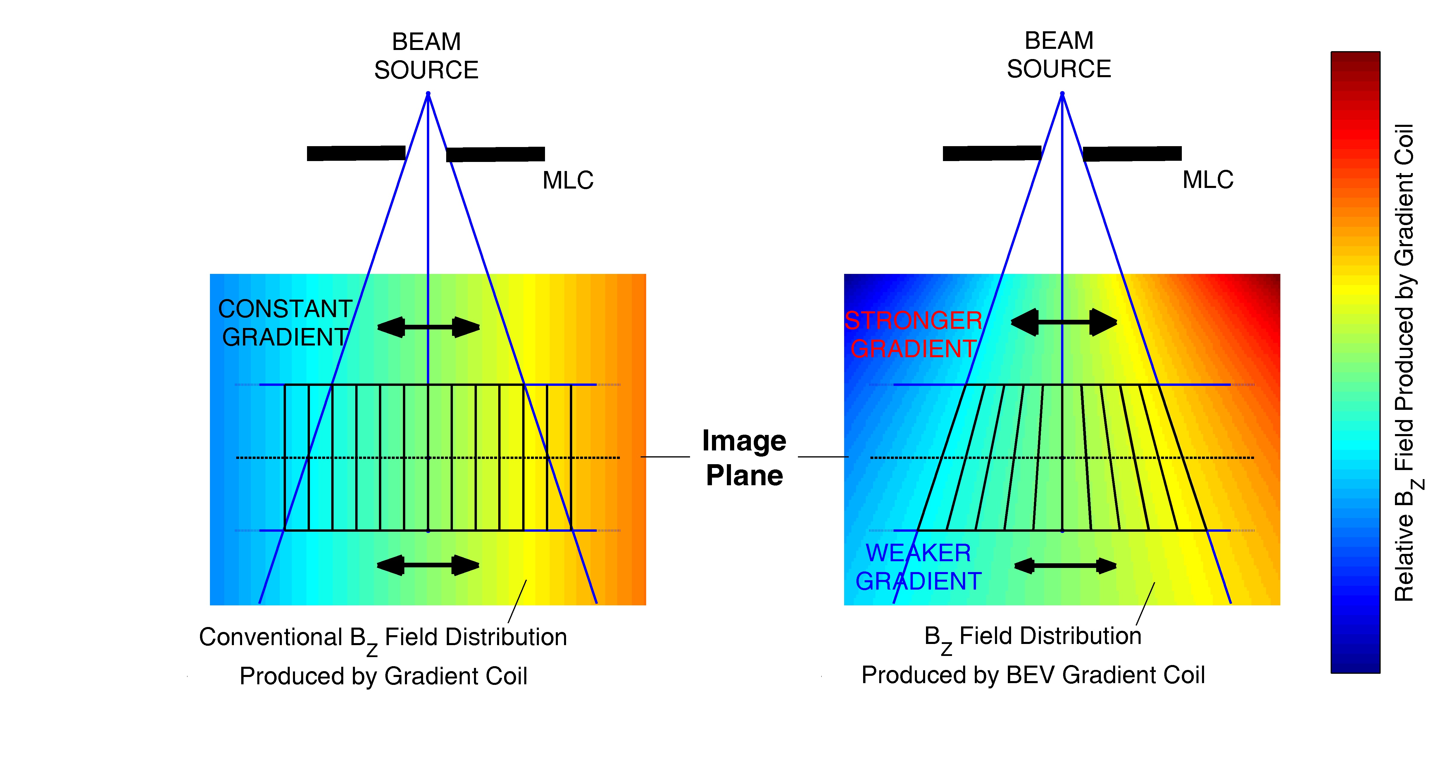
The encoding gradients must clearly be altered in order to accommodate this new geometry. If the radiation source is fixed relative to the MR unit, only the two gradients perpendicular to the beam direction need be modified, as a divergent geometry can be generated with parallel slice boundaries as seen in Figure 1B. The in-plane gradients will have to modified to provide an increasing signal compression as one moves towards the beam source. This compression will correspond to an increasing in-plane gradient strength, allowing each "divergent" pixel to be encoded with the same gradient field (Figure 2). As opposed to the conventional in-plane gradients which can be described as
$$$G_{i}\left ( x,y,z \right ) \propto \hat{r}_{i} \cdot \left \langle x,y,z \right \rangle$$$,
the increasing gradient strength in the direction of the beam source can be described as
$$$G_{i}\left ( x,y,z \right )\propto \frac{SID}{SID+\hat{r}_{s}\cdot \left \langle x,y,z \right \rangle} \hat{r}_{i}\cdot \left \langle x,y,z \right \rangle$$$,
where $$$\hat{r}_{i}$$$ is a unit vector pointing in the direction of one of the in-plane gradients, and $$$\hat{r}_{s}$$$ is a unit vector pointing from the beam source toward isocentre. $$$SID$$$ represents the distance between the source and isocentre.
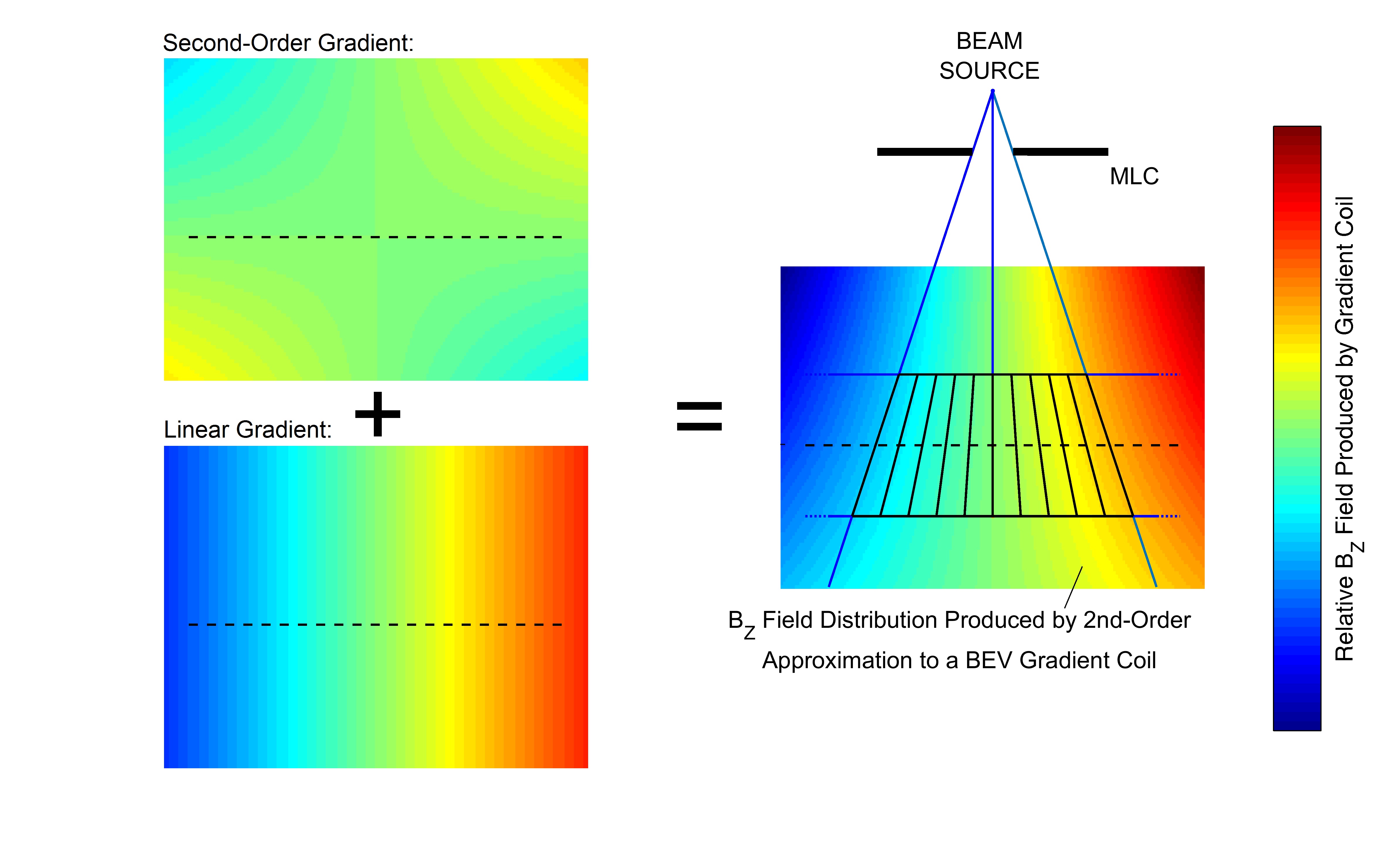
This solution will only function when the in-plane gradients are fixed relative to the beam-source. However, in some implementations of these MRI-radiotherapy hybrids, the source is made to rotate about a fixed MRI. In this circumstance there is no one gradient coil that can produce an in-plane BEV gradient for all source orientations. However, despite the fact that the ideal BEV gradient field does not vary linearly with distance to the source, a combination of a conventional linear gradient and a second-order field pattern can approximate the distribution well over small regions of space (Figure 3). The required second-order field pattern will be a product of the distance from isocentre in the direction of the in-plane gradient, and the distance from isocentre in the direction of the source, and its weighting determined numerically based on the slice thickness and position. Two such gradients would be required for any one orientation, with a combination of four providing a basis set for all source positions.
Methods
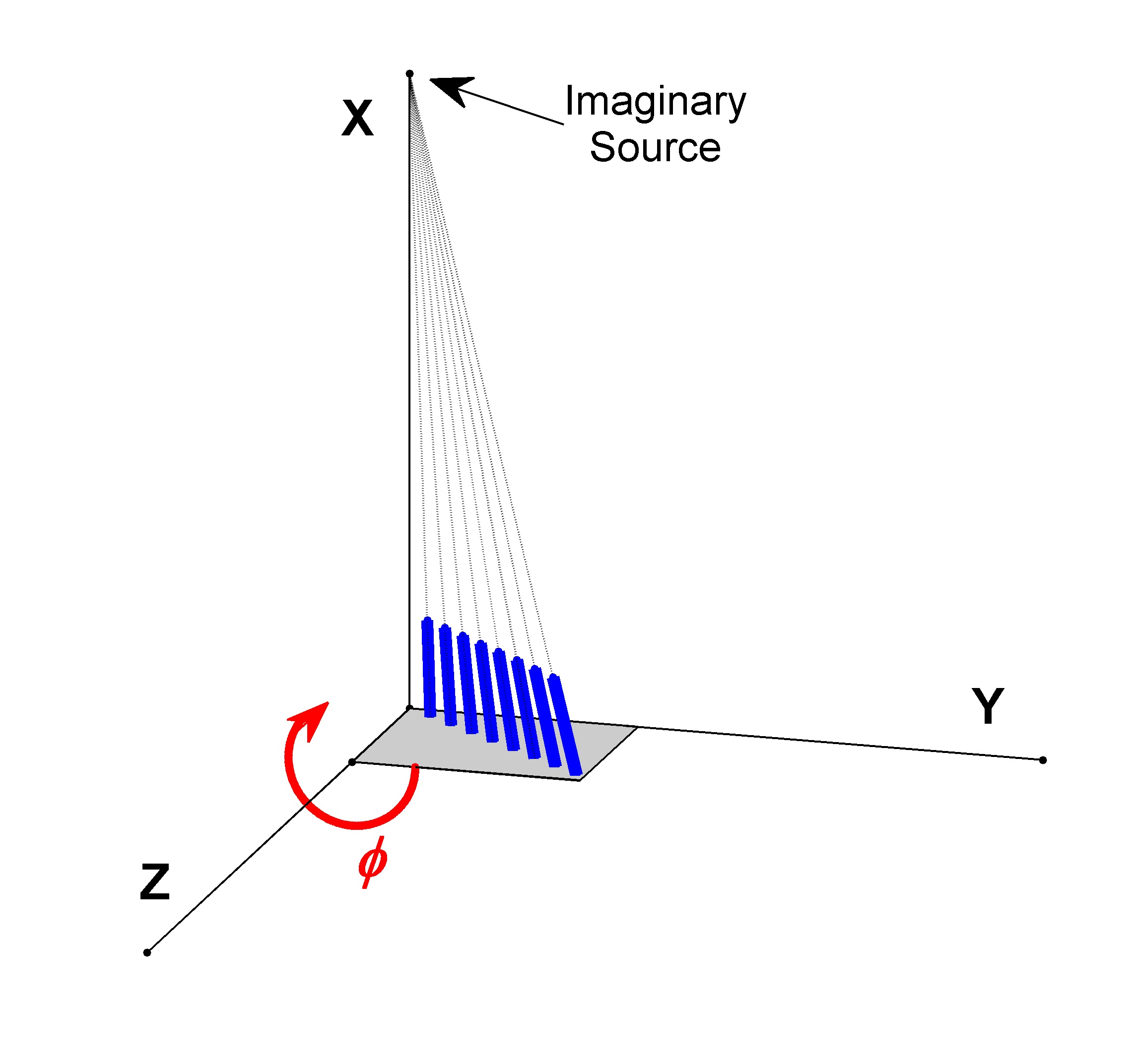
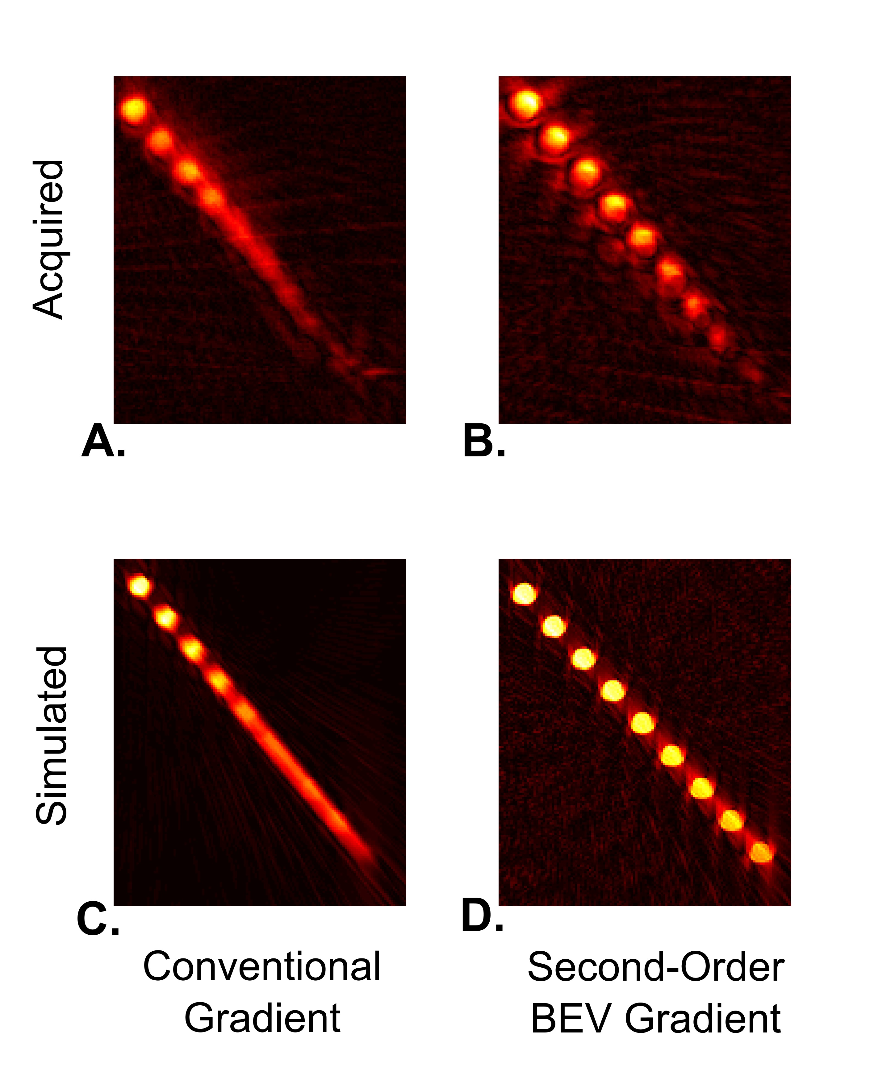
A series of 12-cm gelatin rods were arranged to converge upon an imaginary source 100-cm away as depicted in Figure 4. This phantom was then placed with the base of the untilted rod at isocentre and rotated about this point by an arbitrary 26 degrees. The phantom was imaged with a 12-cm slice using a centre-out radial sequence with a 150-μs TE, and 102 spokes. The sequence was then repeated 102 times with the 2nd-order shim gradients manually configured to create the ideal second-order field for one of the particular spokes. For this orientation the ZY, XZ, 2XY, and X2-Y2 gradients were used as the basis set, and at any one time the combination of shims created a second-order field of 5.263 mT/m2, accompanying the read-encoding gradient with strength of 4.639 mT/m. This manual process was required as shim gradients are not made capable of switching rapidly in conjunction with the linear encoding gradients.
A simulation of the same phantom was acquired using the same radial sequence and reconstructed the same way (filtered back-projection).
Results and Conclusion
The acquired and simulated images of the phantom are shown in Figure 5. The BEV-approximated gradients yielded much clearer images of the individual gel rods as did the conventional.Acknowledgements
The authors gratefully acknowledge the Alberta Cancer Foundation for support.References
- Fallone BG. "The rotating biplanar linac–magnetic resonance imaging system." Seminars in Radiation Oncology 24(3):200-202, 2014.
- Keall PJ, Barton M, Crozier S. "The Australian magnetic resonance imaging–linac program." Seminars in Radiation Oncology 24(3):203-206, 2014.
- Green OP, Goddu S, Mutic S. "Commissioning and Quality Assurance of the First Commercial Hybrid MRI‐IMRT System." Medical Physics 39(6):3785, 2012.
- Lagendijk JJ, Raaymakers BW, Raaijmakers AJ, Overweg J, Brown KJ, Kerkhof EM, van der Put RW, Hårdemark B, van Vulpen M, van der Heide UA. "MRI/linac integration." Radiotherapy and Oncology 86(1):25-29, 2008.
Figures