0944
Rotatable Main Field MRI Scanner for Angle Sensitive Imaging1Mechanical Engineering, Imperial College London, London, United Kingdom, 2Electrical Engineering, Imperial College London, London, United Kingdom
Synopsis
Anisotropies with respect to the main field direction in collagen-rich tissues may be exploited to provide new information about the tissue microstructures. However this requires the field to be oriented at various oblique angles relative to the subject. This is usually difficult and often impossible using conventional MRI magnet configurations. We have developed an entirely new open magnet concept which can be rotated about two motorised axes to achieve a wide range of orientations. The design of the magnet and the gradients posed special challenges. The new MRI system is suitable for imaging of extremities, particularly the knee.
INTRODUCTION
Field-related anisotropies of collagen include magic angle effects due to unaveraged dipolar interactions of proton nuclear spins1,2 and orientation-dependent magnetic susceptibility3,4. Angle sensitive MRI data may be exploited to provide valuable new information about tissue microstructures2-5, such as collagen fibre tracts, potentially leading to significantly improved diagnostic methods. Unfortunately, varying field orientation for in-vivo human imaging is very difficult or impossible using conventional magnet configurations, both with the closed bore cylindrical and the conventional open magnets6.
To address this issue, we have developed an entirely new open magnet concept7, aimed at extremity imaging, allowing a wide range of orientations to be achieved by rotating the magnet about two orthogonal axes. The key challenges were the design of a compact main magnet which produces its net main field parallel to the poles, and the design of gradients compatible with this magnet configuration and aspect ratio, while maximizing linearity.
METHODS
The permanent magnet pole pieces each present a North and South pole in a symmetrically opposing arrangement, consisting of arrays of discrete rectangular magnets, modulated in height and polarity in order to achieve a uniform field in the central imaging volume. Specially developed modelling and optimisation codes were employed to control the evolving magnet configuration, providing input models for commercial finite element software. The magnet design also incorporates passive shimming sets, comprising arrays of small permanent magnets, conveniently located within the recess formed by the main magnet blocks without affecting the net pole gap.
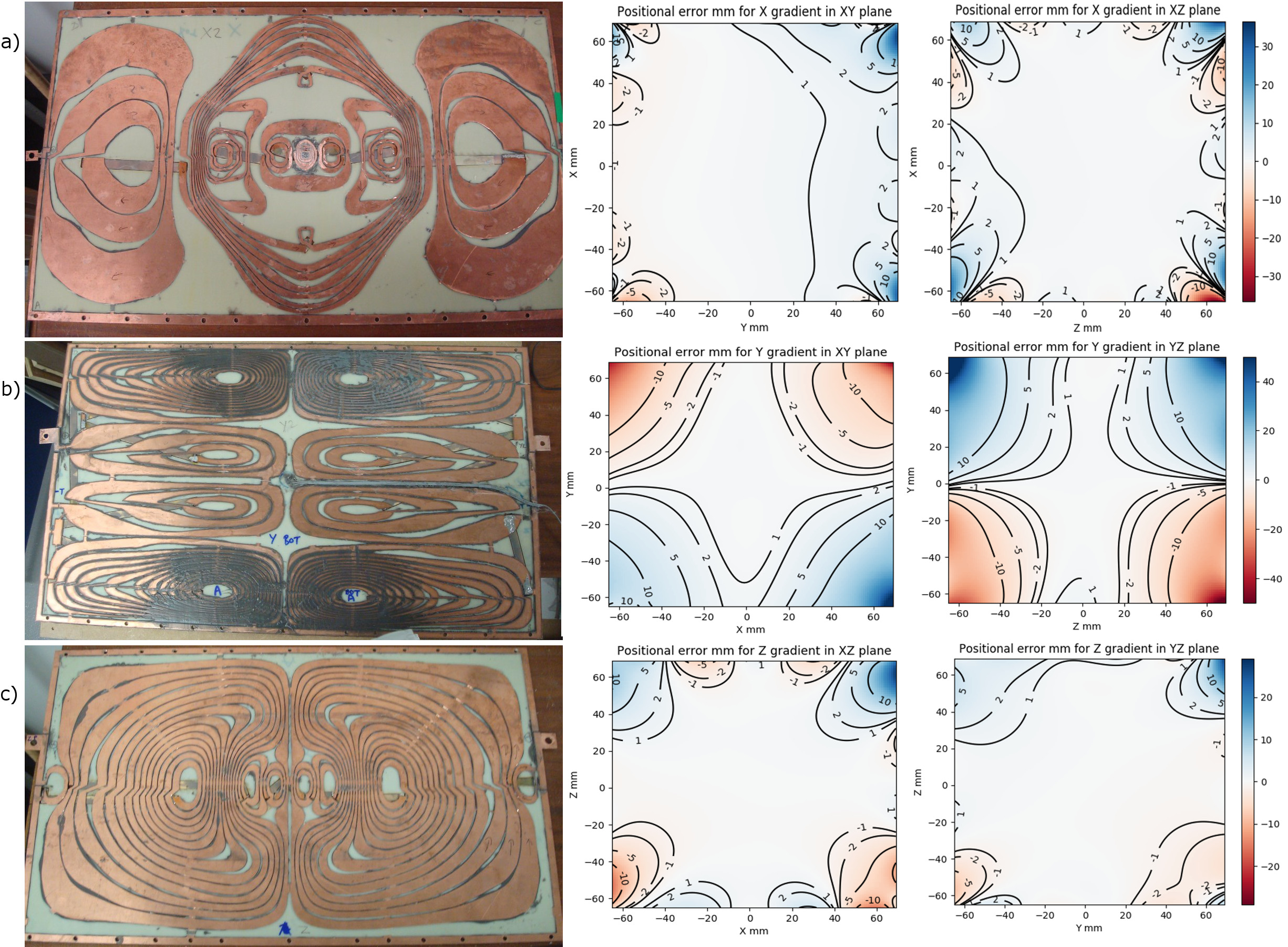
Pole-mounted gradient coil design posed particular challenges due to the magnet main field orientation and the aspect ratio. Note that for the transverse field magnet the gradient coil arrangement is quite different from that of a conventional open magnet for which two of the three coil sets are much simpler and have the same pattern. In our case, the y-axis gradient involves a particularly demanding tight arrangement of multiple coils along the shorter dimension of the magnet. The design was performed using specially developed constrained optimisation codes using sequential quadratic programming, aiming to maximise linearity while ensuring manufacturability. The coils were manufactured using water jet cutting. In view of the sensitivity of permanent magnets to temperature changes, the gradient stack includes additional coils providing controlled B0 compensation. A novel system using heat pipes (sealed 2-phase cooling) is also incorporated to minimise any heating from the gradients.
Following construction, magnet and gradient performance were measured at high resolution using a robotised NMR probe.
RESULTS
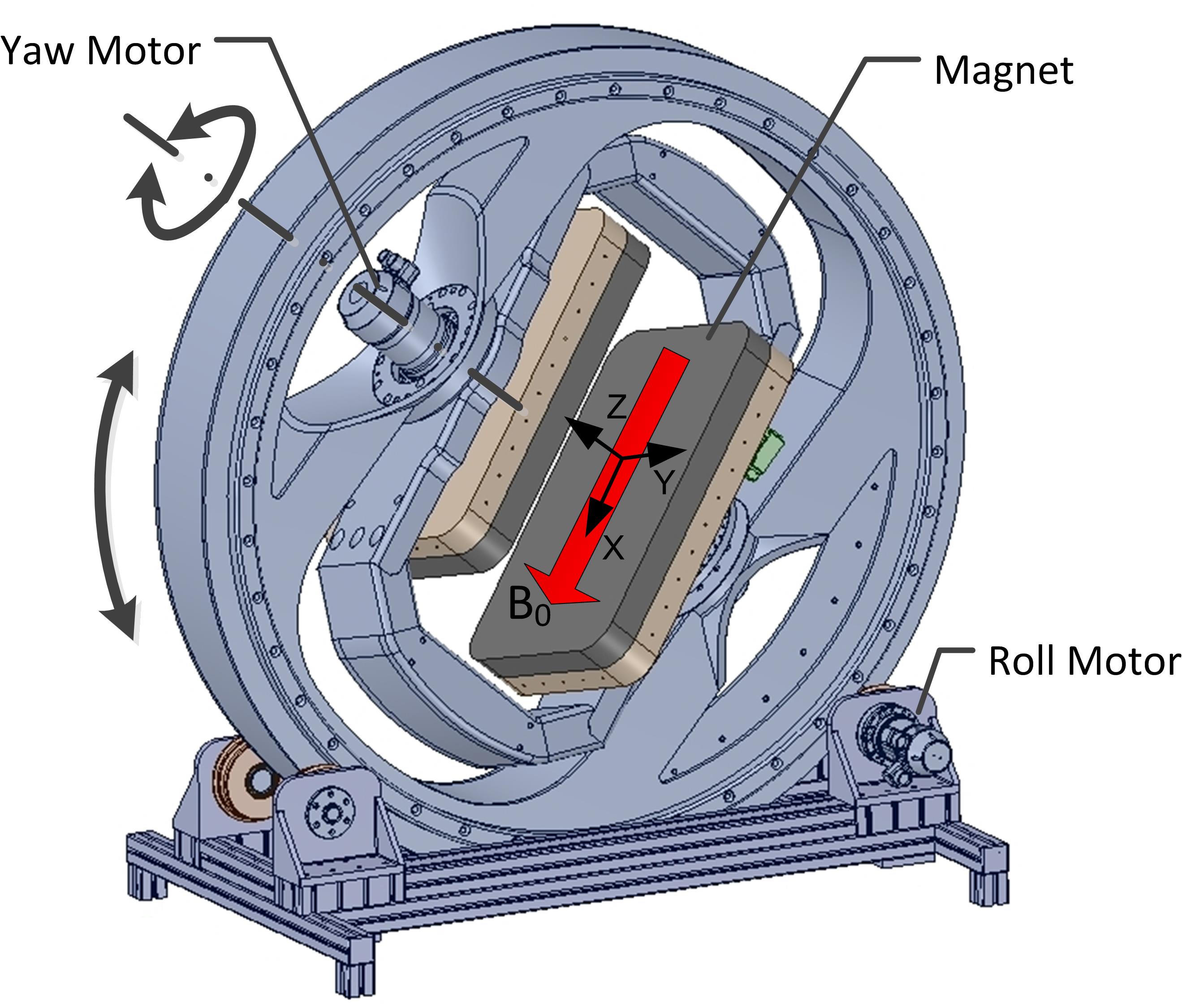
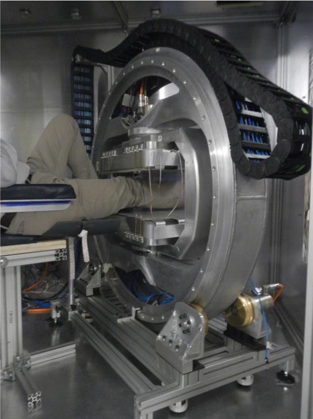
Fig.1 shows the configuration of the moveable magnet indicating the field direction and the degrees of freedom. The pole piece dimensions are 600mm x 350mm, net pole gap is 220 mm, field strength 0.15T in a 150mm DSV. The outer ring (1300 mm diameter) is supported by the rollers at the base to provide full 360° ‘roll’. The inner frame can be rotated to provide ‘yaw’ rotation and it is limited to ±50° using adjustable mechanical stops. Fig. 2 shows the complete system installed in our laboratory.
The gradient coils are capable of producing >20 mT/m in a rise time of <0.2ms. Fig.3 shows the manufactured coils and the measured performance expressed as contours of constant image distortion in millimetres. Fig.4 shows an early test image of a phantom (resolution 0.5mm).
DISCUSSION
Consideration of the magic angle effect shows that a maximum signal strength may be achieved at θ=55° relative to the collagen structures, so a rotation range of ±55° for each axis would achieve all necessary angulations. However, by allowing full 360° rotation of the roll axis, the yaw range does not need to be larger than ±35°, allowing significantly improved ergonomics.
Gradient design was aimed at maximising linearity and therefore minimising 3D geometrical distortion of images, which need to be obtained at different magnet orientations and correlated. The achieved performance represents a satisfactory compromise in the presence of magnet constraints. If necessary, additional image corrections may be readily applied using the recorded detailed field mapping data.
CONCLUSION
The prototype MRI system is capable of achieving a full range of required field orientations needed for in-vivo human studies of field-angle related anisotropies of collagen, enabling future studies to establish new diagnostic methods. Existing MRI methods are insufficient for accurate diagnostics of ligaments, cartilage and tendons, leading to invasive procedures such as arthroscopy or surgery. The new system has the potential to enable MRI to become the diagnostic gold standard in such situations.Acknowledgements
This work was supported by the National Institute for Health Research (NIHR) i4i grant II-LA-1111-20005.References
- Fullerton, G.D., and Rahal, A. Collagen structure: the molecular source of the tendon magic angle effect’, J Magn Reson Imaging 2007;25(2):345-361.
- Szeverenyi, N.M., and Bydder, G.M. Dipolar anisotropy fiber imaging in a goat knee meniscus’, Magn Reson Med. 2011;65(2):463-470.
- Liu, C., Susceptibility tensor imaging. Magn Reson Med. 2010; 63(6):1471–1477.
- Wei, H., Gibbs, et al. Susceptibility tensor imaging and tractography of collagen fibrils in the articular cartilage’, Magn Reson Med. 2017.
- Garnov, N., Gründer, W., et al. In vivo MRI analysis of depth‐dependent ultrastructure in human knee cartilage at 7 T, NMR Biomed. 2013;26 (11):1412-1419.
- Tse, Z.T.H., Elhawary, H., Zivanovic, A., Rea, M., Paley, M., Bydder, G., Davies, B.L., Young, I., and Lamperth, M.U.: ‘A 3-DOF MR-compatible device for magic angle related in vivo experiments’, IEEE ASME Trans Mechatron 2008;13(3):316-324.
- McGinley J. V., Ristic M. and Young I. R., "A permanent MRI magnet for magic angle imaging having its field parallel to the poles," J Magn Reson 2016; 271:60-67.
Figures