0943
A 6.3kg Single-Sided Magnet for 3D, Point-of-Care Brain Imaging1Massachusetts Institute of Technology, Cambridge, MA, United States, 2Athinoula A Martinos Center for Biomedical Imaging, Charlestown, MA, United States, 3Harvard Medical School, Boston, MA, United States
Synopsis
MRI, as currently used, requires transporting the patient to the scanner. A truly point-of-care MRI device, possibly even hand-held, could increase the utility of MRI extending its reach and enabling new applications, such as continuous bedside monitoring. In this work, we design and construct a light-weight (6.3kg), single-sided permanent magnet designed to image the cortical region it is positioned over (~8cm x 8cm x 3cm ROI). We describe the magnet optimization and compare the predicted and measured B0 field pattern and validate its imaging potential by acquiring 1D depth profiles in a phantom.
Introduction
Size, expense and siting issues prohibit conventional MRI systems from point-of-care use in almost all clinical settings. Although effort is building toward inexpensive, easily-sited systems for rural, developing-world, or even bedside settings1,2 and considerable work has been put into single-sided MR devices for rock and materials characterization3–7 only a few studies8 have focused on highly portable, or hand-held devices for medical applications. In this work, we assess the feasibility of a lightweight single-sided device capable of imaging a few centimeters into the human brain. We optimize a rare-earth permanent magnet array for this purpose in a “cap-like” configuration, and show that a ~8x8x3cm3 imaging region can be achieved with reasonable field gradient in depth and a mean $$$\bar{B}_{0}$$$ of about $$$64mT$$$, proton freq. = 2.7MHz. We validate the magnet performance with 1D depth profile images from a multiple-disc phantom.Methods
The starting point for the cap-shaped magnet was an
equatorial portion of a “Halbach Sphere”9 . This magnetization pattern
was discretized into 37 blocks, whose compositions and positions were then optimized
using a genetic optimization in Matlab (Mathworks, Natick MA). Blocks were allowed
to use one of 7 easily procurable material/size combinations varying from empty/non-magnetic
through an N52 NdFeB material, 1”x1”x1.375” block. The genetic algorithm also had
the ability to shift all blocks along $$$\hat{x}$$$ by $$$\pm 1cm$$$, and to shift 6 blocks along
$$$\hat{y}$$$ by $$$\pm 1cm$$$. The
cost function employed the percent variation in magnetic field over an ROI;
mean $$$|\bar{B}_{0}|$$$ was constrained to be at least $$$50mT$$$; and magnet symmetry about
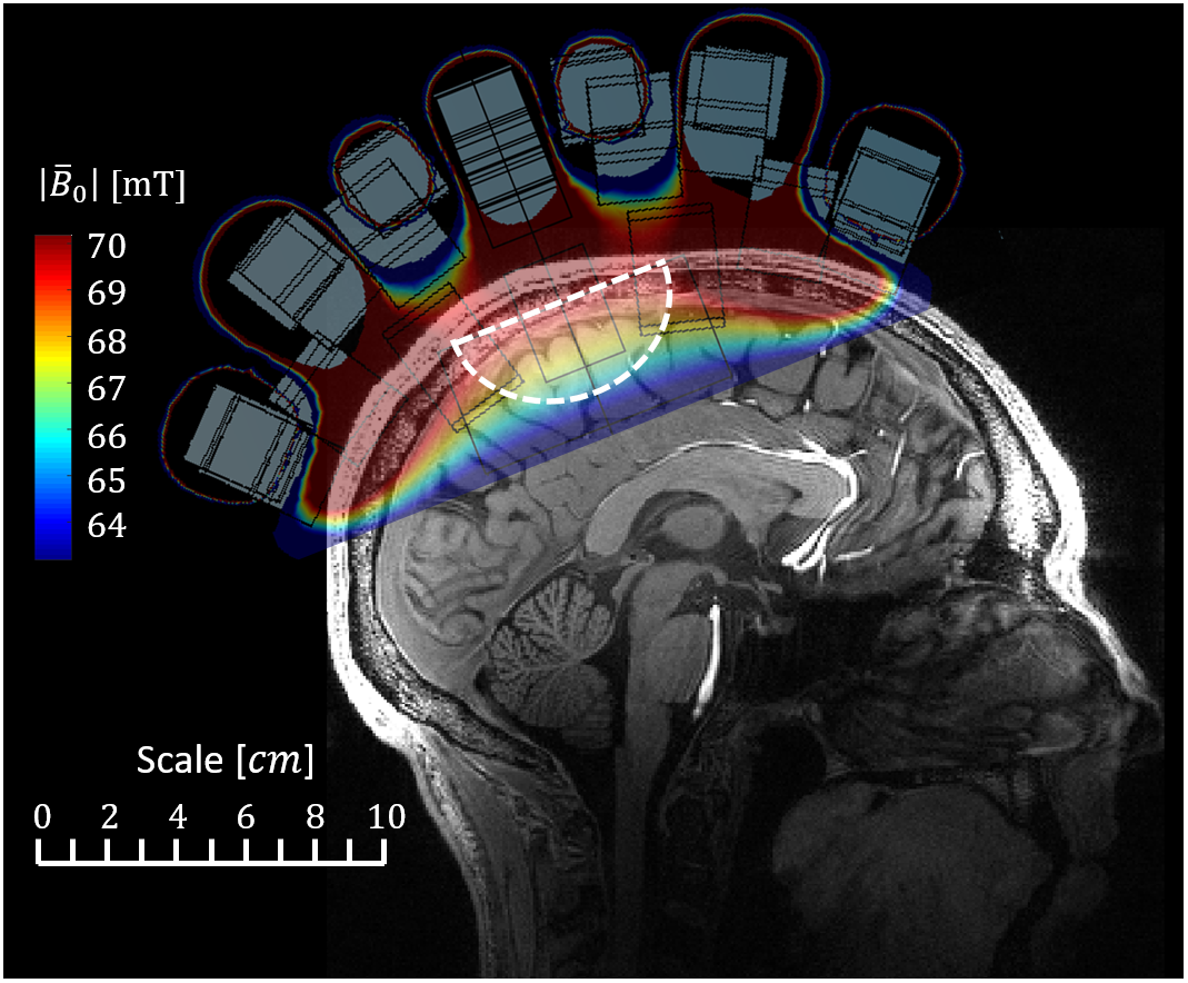
the x-y and x-z planes was imposed. A hemi-ellipsoidal
ROI with $$$4cm$$$ major radii and a $$$3cm$$$ minor radius was used. This ROI penetrates $$$3cm$$$ into cerebral cortex (Figure 1) and roughly matches
the excitation region of a loop Tx coil. $$$|\bar{B}_{0}|$$$ maps were analyzed using COMSOL (COMSOL Inc,
Burlington MA).
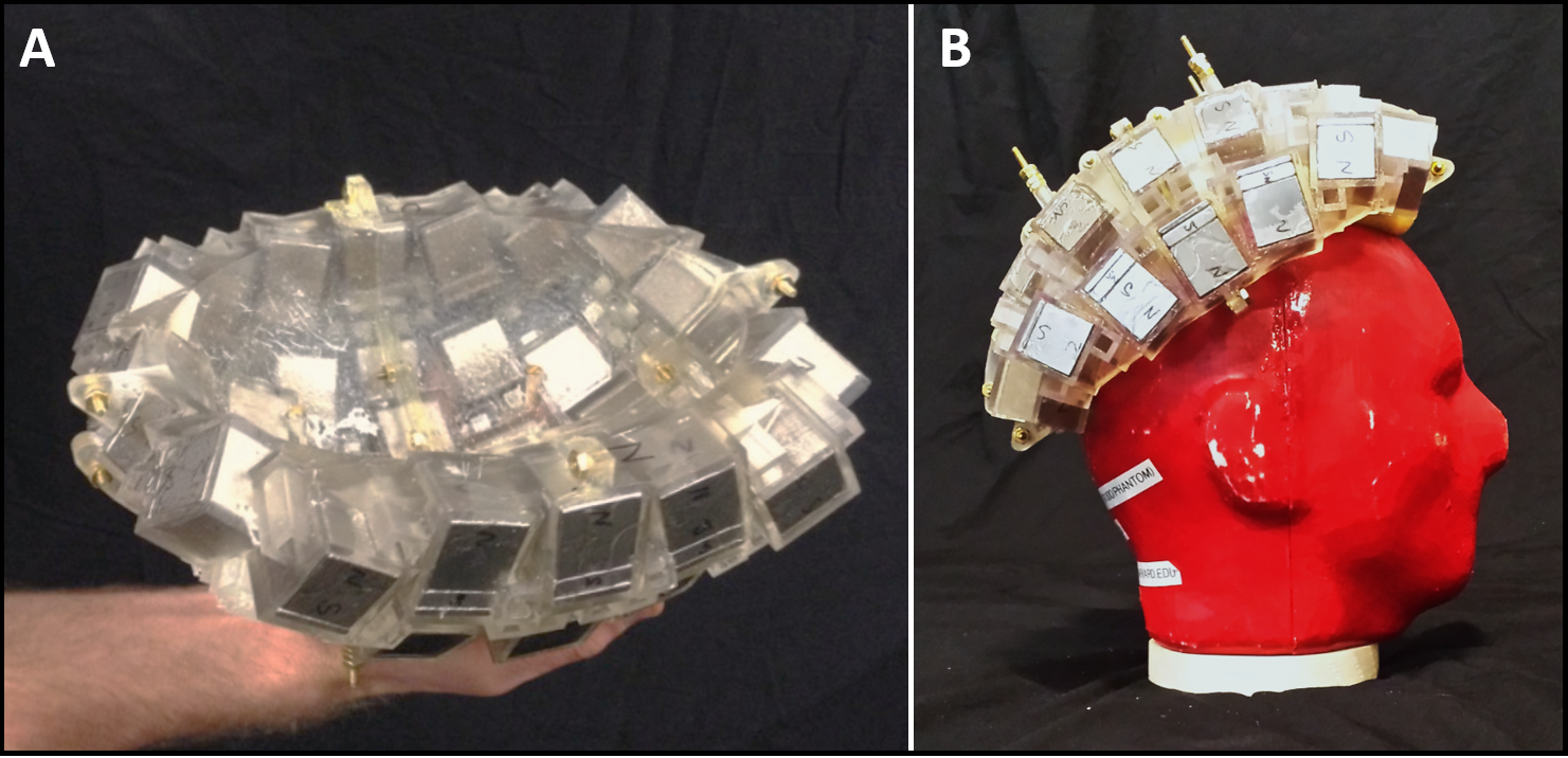
After the optimal design was chosen, a former to hold the
magnets was constructed with 3D printing (Formlabs Form2, Somerville MA). The prescribed
NdFeB magnets (Applied Magnets, Plano TX), were then epoxied into the former. A
$$$|\bar{B}_{0}|$$$ map was acquired using a 3-axis Hall-effect
magnetometer (Metrolab, Geneva, Switzerland) moved by a stepper robot.
A , 5-turn Tx/Rx coil was tuned
to $$${f}_{c}=2.685 MHz$$$ and matched ($$$BW (3dB)=150kHz$$$). The coil fit closely about
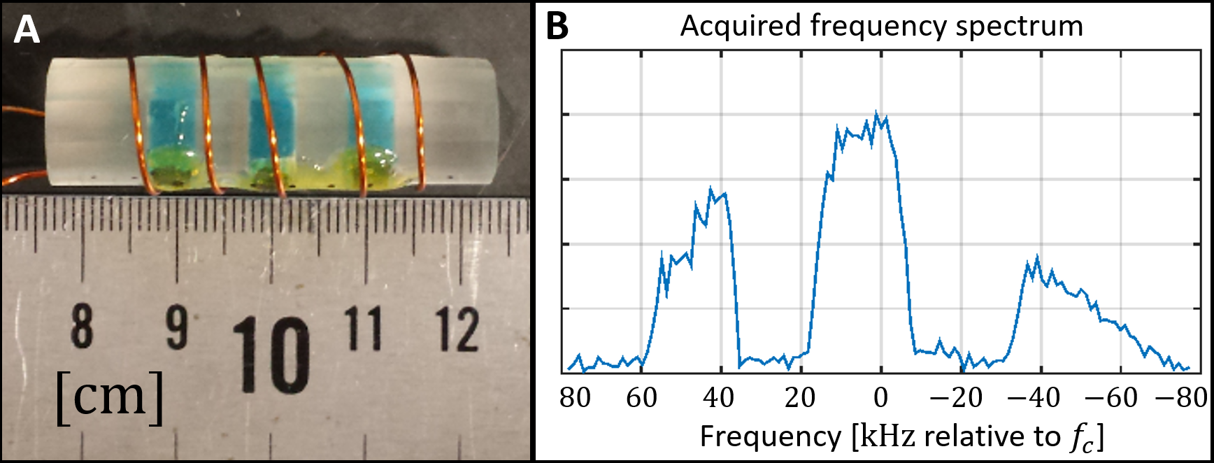
a phantom containing three $$$D=10mm$$$, $$$h=5mm$$$ discs of 0.09% Gd-DPTA solution spaced $$$5mm$$$ apart (Figure 5A). The unshielded phantom and
coil were placed in the sensitive ROI of the magnet, and data were acquired
using a hard pulse TSE sequence ($$${f}_{c}=2.69MHz$$$; echo train length = 6; $$${N}_{ave}=64$$$; 128 samples; $$$BW=1221 \frac{Hz}{Px}$$$; $$$TR=923ms$$$; pulse lengths $$${t}_{90}$$$/$$${t}_{180}$$$=$$$2\mu s$$$/$$$4\mu s$$$).Results
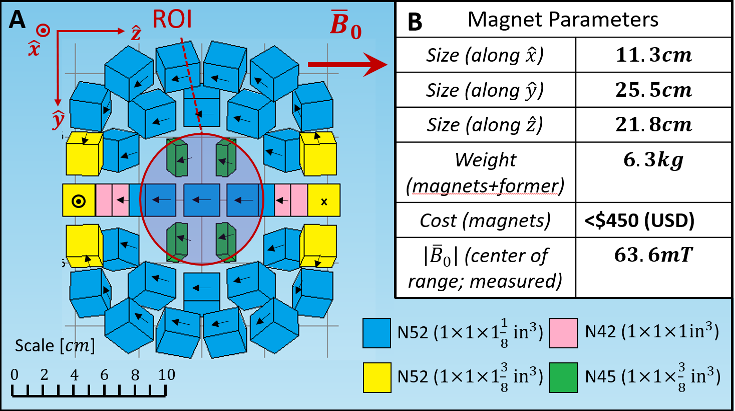
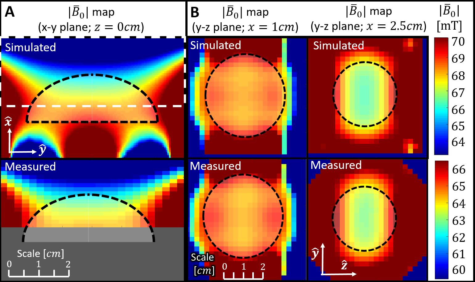
The chosen design utilized blocks with 4 different material/size combinations (Figure 2A), and resulted in a $$$11.3cm\times 22.5cm\times 21.8cm$$$, $$$6.3kg$$$ magnet (Figure 2B). The necessary magnetic material cost under $450 (USD). The constructed magnet could be held and moved by hand, and fit on an 85th-percentile adult male head phantom (Figure 3). Figure 4 shows simulated and measured field maps are shown in the x-y and y-z planes. The magnet’s field was $$$67.5mT$$$ at the ROI center with a field range of $$$4.77mT$$$ across the ROI in the simulations. For the constructed magnet, the corresponding center field and range were $$$63.6mT$$$ ($$$2.71MHz$$$) and $$$4.40mT$$$ ($$$187kHz$$$). The simulated built-in $$$|\bar{B}_{0}|$$$ gradient along the center axis of the magnet varied from $$$154\frac{mT}{m}$$$ to $$$198\frac{mT}{m}$$$ as one moves away from the magnet. For the constructed magnet, the corresponding limits were $$$88\frac{mT}{m}$$$ and $$$174\frac{mT}{m}$$$ Figure 5 shows the acquired spectrum of the 3-disc phantom centered $$$6cm$$$ from the bottom of the magnet “bowl”. Three lobes are visible in the projection, corresponding to three regions of water in the phantom. The local $$$|\bar{B}_{0}|$$$ gradients calculated from these data vary between $$$95\frac{mT}{m}$$$ (near the magnet) and $$$143\frac{mT}{m}$$$ (far from the magnet). For this acquisition, this corresponds to a depth resolution between $$$0.30mm$$$ and $$$0.20mm$$$. The three 1D projection lobes are of different heights, likely resulting from the phantom signal bandwidth ($$$135kHz$$$) being near the Tx/Rx coil bandwidth ($$$150kHz$$$).Discussion
We have demonstrated a novel design of a low-cost, lightweight (<$450 (USD), 6.3kg) single-sided magnet for point-of-care 3D brain imaging. As the initial work towards 3D imaging, we have shown the ability of this magnet to perform high-resolution (0.2 to 0.3mm) depth profiling along the 2.5cm length of phantom. Our next steps will be to add single-sided gradient coils for phase encoding along the other two spatial dimensions and enable full 3D imaging.Acknowledgements
NIH: 5T32EB1680, R01EB018976; Thomas Witzel for help with the Apollo consoleReferences
1. Vaughan JT, Wang B, Idiyatullin D, Sohn S, Jang A, BelaBarra L, Garwood M. Progress Toward a Portable MRI System for Human Brain Imaging. In: ISMRM. ; 2016. p. 498.
2. Cooley CZ, Stockmann JP, Armstrong BD, Sarracanie M, Lev MH, Rosen MS, Wald LL. Two-dimensional imaging in a lightweight portable MRI scanner without gradient coils. Magn. Reson. Med. [Internet] 2015;73:872–83. doi: 10.1002/mrm.25147.
3. Jackson JA. Remote NMR well logging. Geophysics 1981;46:415.
4. Goga NO, Demco DE, Kolz J, Ferencz R, Haber A, Casanova F, Blu B. Surface UV aging of elastomers investigated with microscopic resolution by single-sided NMR. 2008;192:1–7. doi: 10.1016/j.jmr.2007.10.017.
5. Judeinstein P, Ferdeghini F, Oliveira-silva R, Zanotti J, Sakellariou D. Low-field single-sided NMR for one-shot 1D-mapping : Application to membranes. J. Magn. Reson. [Internet] 2017;277:25–29. doi: 10.1016/j.jmr.2017.02.003.
6. Casanova F, Perlo J, Blümich B. Single-Sided NMR. 1st ed. Berlin Heidelberg: Springer-Verlag; 2011.
7. Perlo J, Casanova F, Blümich B. 3D imaging with a single-sided sensor: An open tomograph. J. Magn. Reson. 2004;166:228–235. doi: 10.1016/j.jmr.2003.10.018.
8. Landeghem M Van, Danieli E, Perlo J, Blümich B, Casanova F. Low-gradient single-sided NMR sensor for one-shot profiling of human skin. J. Magn. Reson. [Internet] 2012;215:74–84. doi: 10.1016/j.jmr.2011.12.010.
9. Leupold H, Potenziani II E. Novel High-Field Permanent-Magnet Flux Sources. IEEE Trans. Magn. 1987;MAG-23:3628–3629.
Figures