0841
Towards Real-time MRI Guided Cancer Therapy: Development of a high field Inline MRI-Linac1Ingham Institute, Liverpool, Australia, 2Liverpool Cancer Therapy Centre, Liverpool, Australia, 3University of Queensland, Brisbane, Australia, 4University of Sydney, Sydney, Australia
Synopsis
This study describes the progress that has been made using a dedicated split bore 1.0 Tesla magnet to provide an MRI-guided radiotherapy system. This magnet design has a number of advantages including patient entry in two orientations to investigate competing magnetic field-beam configurations. A number of beam and imaging experiments, including first in vivo results, are described which show the efficacy of the system as an integrated inline MRI-Linac.
Introduction
The pursuit of real-time MR guided radiotherapy has seen the emergence of several hybrid systems combining a linear accelerator with an MRI scanner. There are two main configurations being investigated, with the radiation beam either parallel (inline) or perpendicular to the magnetic field. Following previous phase I experiments, with a mega voltage beam delivered into the bore of a 1.5 Tesla clinical scanner,1 we describe here progress that has been made in phase II using a dedicated open magnet. This magnet design has a number of advantages including patient entry in either orientation.2 Results are presented which show the acceptance and integration of the system as a high field inline MRI-Linac.Materials & Methods
A bespoke 1.0 T magnet (Agilent, UK) has been designed with a 50 cm gap and 60 cm diameter bore, to permit beam and patient entry in either orientation. It is actively shielded to produce a zero Gauss region at 1.2-1.4 m from isocentre. Imaging gradients consist of two modules (Tesla, UK) in both halves of the magnet. A transmit/receive RF coil (Magnetica, Australia) was designed to fit inside the gap with no obtrusion: This results in a large open space inside the magnet with an unobstructed patient view. A second 6-channel receive only coil was developed for small animal and peripheral imaging. The transmit/receiver switch and control system was a modified 1.5 T Avanto (Siemens) system.
The treatment unit comprises a portable linear accelerator (6 & 4 MV) and multi-leaf collimator (MLC) (Varian) mounted on a rail system allowing changes in surface-to-isocentre distance (SID).
A number of beam and imaging experiments were conducted to demonstrate the efficacy of the system:
(i) Simultaneous beam-on imaging. As part of these tests, shielding around the xray head was used and correct alignment was established using a dedicated test object to rectify beam loss in the magnetic field at various positions. Beam-on imaging experiments were then conducted using a phantom to assess any presence of radiation induced noise1.
(ii) Image quality assurance & geometric integrity. Daily SNR was measured in a large diameter phantom using the image subtraction method. A large FOV distortion phantom was used3 to measure geometric accuracy and used subsequently to correct for system distortion.
(iii) Dynamic control of treatment beam. A trueFISP sequence was configured for this system, and dynamic images were acquired while a phantom was moved inside the bore. Reconstruction was modified to enable segmentation in real-time to determine the target position and this information was sent to the MLC control unit.
(iv) Volunteer imaging studies. Following phantom and in vivo RF heating measurements to verify safety using an MR compatible thermometer, subjects were imaged to evaluate image quality and develop patient treatment protocols. Scans were repeated on a clinical 3 Tesla closed bore system to compare compliance of the new magnet design and to independently assess geometric accuracy.
Results
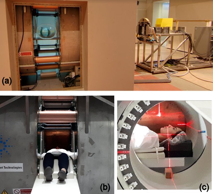
Figure 1 shows a photograph of the completed system. Congruence of the radiation and imaging isocentre to within 2 mm was established prior to imaging.
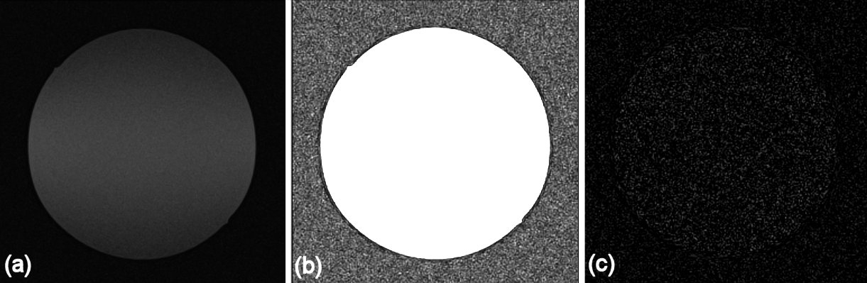
The transmit/receive coil produced artefact free images with excellent uniformity and SNR and negligible effect (<0.5%) from the radiation beam1 (Figure 2). Daily SNR was 42.6 ± 0.9 (mean ± SD) over a period of 3 months. A 5-fold increase in SNR was obtained using the receive-only coil.
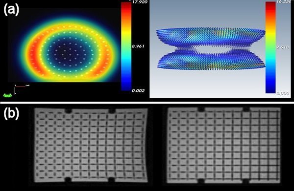
System distortion was found to be disc shaped around the isocentre with smallest distortion in a region of approximately 18 (x) ×18 (y) × 16 (z) cm (Figure 3 (a)). This was confirmed using registration of brain images with corresponding scans acquired with a high bandwidth protocol at 3 T which showed negligible difference. Outside of this low distortion region, correction was successfully employed to reduce errors to < 2 mm (Figure 3 (b)).
Real-time images were successfully streamed onto the treatment delivery system and used to dynamically control the MLC movement at a rate of 3 frames per sec.
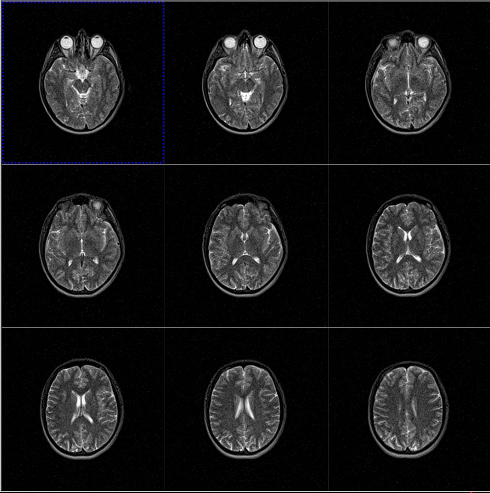
Volunteer testing demonstrated negligible RF heating and no stimulation. Figure 4 shows example images obtained with the integrated RF coil. Imaging protocols have been developed for both simulation and fast treatment time images (19 s per beam angle) which were shown to accurately verify patient translation and rotation for supine, prone and oblique set-ups.
Conclusions
A bespoke MRI system comprising an open magnet with dedicated gradient & RF hardware has been described. This has been successfully integrated with a linear accelerator unit to provide a complete system capable of providing real time MR-guided radiotherapy. Imaging has exceeded expectations in terms of quality and compliance is excellent. On-going work will now focus on radiation beam modelling in the presence of the magnet field and work-up towards clinical trials.Acknowledgements
No acknowledgement found.References
[1] Keall PJ, et al. Semin Radiat Oncol 2014; 24:203-205.
[2] Liney GP, et al. Med. Phys. 2016; 43: 5188-5194.
[3] Walker A, et al. Med Phys 2015; 42: 1982-1991.
Figures