0839
MAGNUS: An ultra-high efficiency head-only gradient coil for imaging the brain microstructure1GE Global Research, Niskayuna, NY, United States, 2GE Healthcare, Florence, SC, United States, 3Uniformed Services University of the Health Sciences, Bethesda, MD, United States, 4Ft. Belvoir Community Hospital, Ft. Belvoir, VA, United States
Synopsis
An ultra-high gain asymmetric gradient coil design for imaging the brain microstructure is described. This design has greater than 4 times the gain of existing whole-body gradient coils and 3x that of the Compact 3T gradient coil with similar inner diameter. With a 1 MVA driver, this gradient coil is designed to deliver 200 mT/m at a maximum slew rate of 500 T/m/s.
Purpose
In typical MRI gradient designs, maximum use of the magnet warm bore is made to provide the widest patient bore possible. This includes the recent Compact 3T (C3T) magnet where a 42-cm inner diameter (ID) gradient coil was designed for a 62-cm warm bore in a low-cryogen magnet [1], and whole-body 3T magnets with 63-74 cm ID gradients in 89-91 cm magnet warm bores. Smaller gradient diameter head-only gradient coils have demonstrated substantially higher peripheral nerve stimulation thresholds compared to whole-body gradient coils, allowing slew rates greater than 700 T/m/s to be safely achieved, especially for EPI pulse sequences [2,3]. The substantially higher PNS threshold for head-gradient coils has led to marked reduction in spatial distortion and signal dropout characteristic of EPI acquisitions [4]. However, higher maximum gradient amplitudes are still needed in order to study the brain microstructure. This has led to the design of the MAGNUS (Microstructure Anatomy Gradient for Neuroimaging with Ultrafast Scanning) gradient. In comparison to the C3T gradient coil which has a maximum gradient amplitude of 80 mT/m and 700 T/m/s slew rate, the MAGNUS gradient is designed to achieve 200 mT/m and 500 T/m/s with the same 1 MVA gradient driver, and maintain a 42-cm ID.Methods
In the design of the self-shielded C3T gradient coil, the separation between the primary coil layer and the shield layer [5,6] was 9-cm radially. The small primary-shield coil separation reduces the efficiency and gain of the gradient coil. To increase the gradient coil gain, the MAGNUS coil is designed to utilize the full 90-cm warm bore of a whole-body 3T magnet. The primary-shield layer separation is increased to 23 cm, resulting in an approximately 30% increase in maximum gradient amplitude for the same applied driver current.
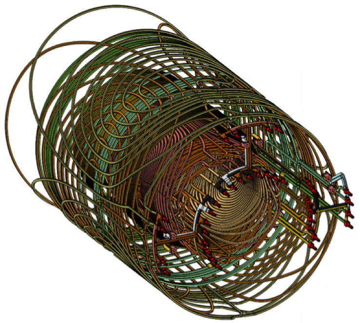
To further increase the gain, a double-layer primary coil design is used. This allows the current density to be substantially increased while controlling the physical turn density for the wire paths to be within a manufacturable range. The double-layer design for the primary coils also better controls the overall coil inductance to achieve slew rate of at least 500 T/m/s. The gradient coil 42-cm ID maintains compatibility with RF coils and patient handling developed for the C3T system. Similar to the C3T gradient coil, the MAGNUS head gradient coil has asymmetric transverse x- and y-gradients, and a symmetric z-gradient [7], and are of all-hollow construction to allow dissipation of >50kW of heat.
Results
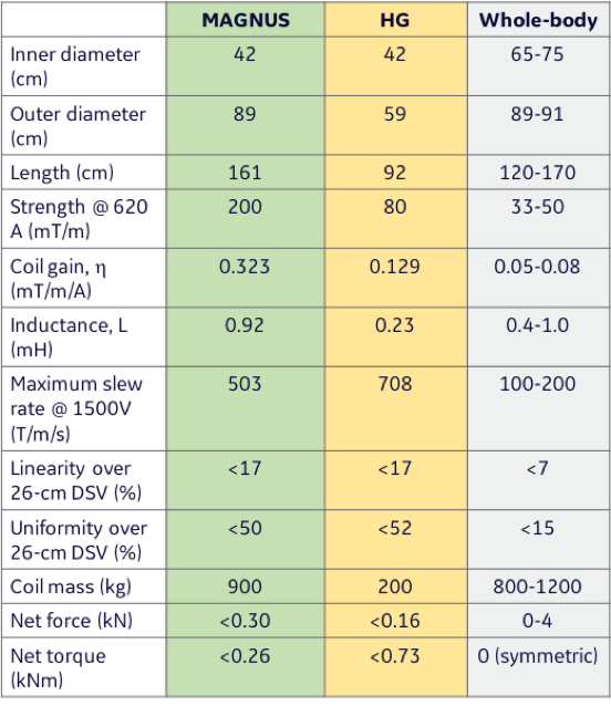
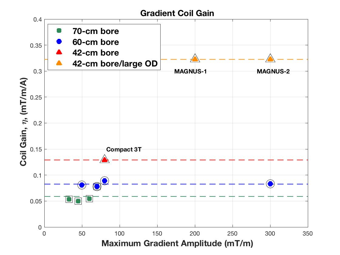
Table 1 shows the design of the MAGNUS gradient compared to a whole-body gradient and the C3T (HG) gradient. By utilizing the available space in a whole-body magnet, the MAGNUS design achieves a coil gain of 0.32 mT/m/A that is 3 times that of the C3T (HG) gradient. The double-layer design and higher turn density results in an increase in inductance from 0.23 mH to 0.92 mH (Figure 4). Accounting for the higher coil gain, this design produces a maximum gradient amplitude of 200 mT/m with 620 A, and a maximum slew rate of 500 T/m/s at 1500 V. This slew rate is still 2.5 times that of a whole-body gradient coil but less than that achieved with the C3T (HG) gradient. As shown in Figure 1, maximum gradient primary-shield separation, as well as the double-layer primary design results in much higher coil gain than in either the C3T (HG) gradient or whole-body gradients, providing a very high efficiency gradient coil for imaging the brain.Discussion
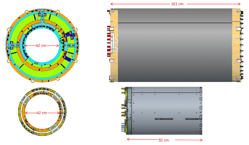
A penalty for achieving such high gradient performance is the size of the gradient. As seen in Figure 2, by utilizing the space available in a whole-body magnet, the MAGNUS gradient is much larger relative to the C3T (HG) gradient. Consequently, the larger estimated weight of the MAGNUS gradient (900 kg vs 200 kg), provides some stiffening of the gradient coil and would reduce the acoustic level from operating at a much higher maximum gradient amplitude. When a 2 MVA gradient driver is used, the MAGNUS design will achieve a maximum gradient amplitude of 300 mT/m at a 730 T/m/s slew rate. This compares favorably with the Connectome gradient that achieves 300 mT/m at a 200 T/m/s slew rate with an 8 MVA driver (per axis) [8].Acknowledgements
Funding support: U.S. Army Medical Research Acquisition Agency Grant W82XWH-16-2-0054. Opinions, interpretations, conclusions and recommendations are those of the authors and are not necessarily endorsed by the Department of Defense or the Uniformed Services University of the Health Sciences.
References
1. Mathieu J-B, Lee S-K, Graziani D, et al. Development of a dedicated asymmetric head-only gradient coil for high-performance brain imaging with a high PNS threshold. Proceedings of the 23rd Annual Meeting of the International Society of Magnetic Resonance in Medicine 2015:1019.
2. Lee SK, Mathieu JB, Piel JE, et al. Brain imaging with a dedicated asymmetric head-only gradient coil without peripheral nerve stimulation at 500 T/m/s. Proceedings of the 23rd Annual Meeting of the International Society of Magnetic Resonance in Medicine 2014:310.
3. Weiger M, Overweg J, Rösler MB, et al. A high-performance gradient insert for rapid and short-T 2imaging at full duty cycle. Magn Reson Med 2017;5:208–11. doi: 10.1002/mrm.26954.
4. Tan ET, Lee S-K, Weavers PT, Graziani D, Piel JE, Shu Y, Huston J, Bernstein MA, Foo TKF. High slew-rate head-only gradient for improving distortion in echo planar imaging: Preliminary experience. J Magn Reson Imaging 2016;44:653–664. doi: 10.1002/jmri.25210.
5. Roemer PB, Hickey JB.Self-shielded gradient coils for nuclear magnetic resonance imaging, Patent No.4,737,716, 1988
6. Turner R, Bowley RM. Passive screening of switched magnetic field gradients. J. Phys. E: Sci. Instrum. 1986;19:876.
7. Roemer PB.Transverse gradient coils for imaging the head, Patent No.5,177,442, 1993
8. Setsompop K, Kimmlingen R, Eberlein E, et al. Pushing the limits of in vivo diffusion MRI for the Human Connectome Project. NeuroImage 2013;80:220–233. doi: 10.1016/j.neuroimage.2013.05.078.
Figures