0837
The orthogonal shim coil at 3-Tesla1High-Field Magnetic Resonance, Max Planck Institute for Biological Cybernetics, Tübingen, Germany, 2Graduate Training Center of Neuroscience, IMPRS, University of Tübingen, Tübingen, Germany, 3A. A. Martinos Center for Biomedical Imaging, Massachusetts General Hospital, Charlestown, MA, United States, 4Harvard Medical School, Boston, MA, United States, 5Electrical Engineering and Computer Science, Massachusetts Institute of Technology, Cambridge, MA, United States, 6Institute of Biomedical Engineering, National Taiwan University, Taipei, Taiwan, 7Department of Neuroscience and Biomedical Engineering, Alto University, Espoo, Finland
Synopsis
We purpose an integrated RF-shim coil array, where the shimming current path and the RF receiving coil are arranged
Purpose
High-quality magnetic resonance imaging and spectroscopic measurements require a highly homogeneous magnetic field in order to minimize various artifacts caused by static or dynamic changes of the main magnetic field (B0). These artifacts can be corrected by providing a compensating magnetic field generated by shim coils. Different from correcting the global magnetic field inhomogeneity by large volume shim coils, localized off-resonance can be corrected by multiple small shim coils(1). Such designs have been realized in arrays of circular shim coils and integrated radio-frequency (RF)-shimming coils(2, 3). However, these designs cause non-negligible interference to RF coils and consequent image quality degradation.
Here we propose a new multi-coil shim array, where shim coils and nearby RF coils are placed on two orthogonal planes. This orthogonal positioning minimizes the interference between RF coils and shim coils, while multiple shim coils provide similar shimming performance like a multi-coil shim array(2). We used both simulations and phantom experiments to evaluate the performance of this design.
Methods
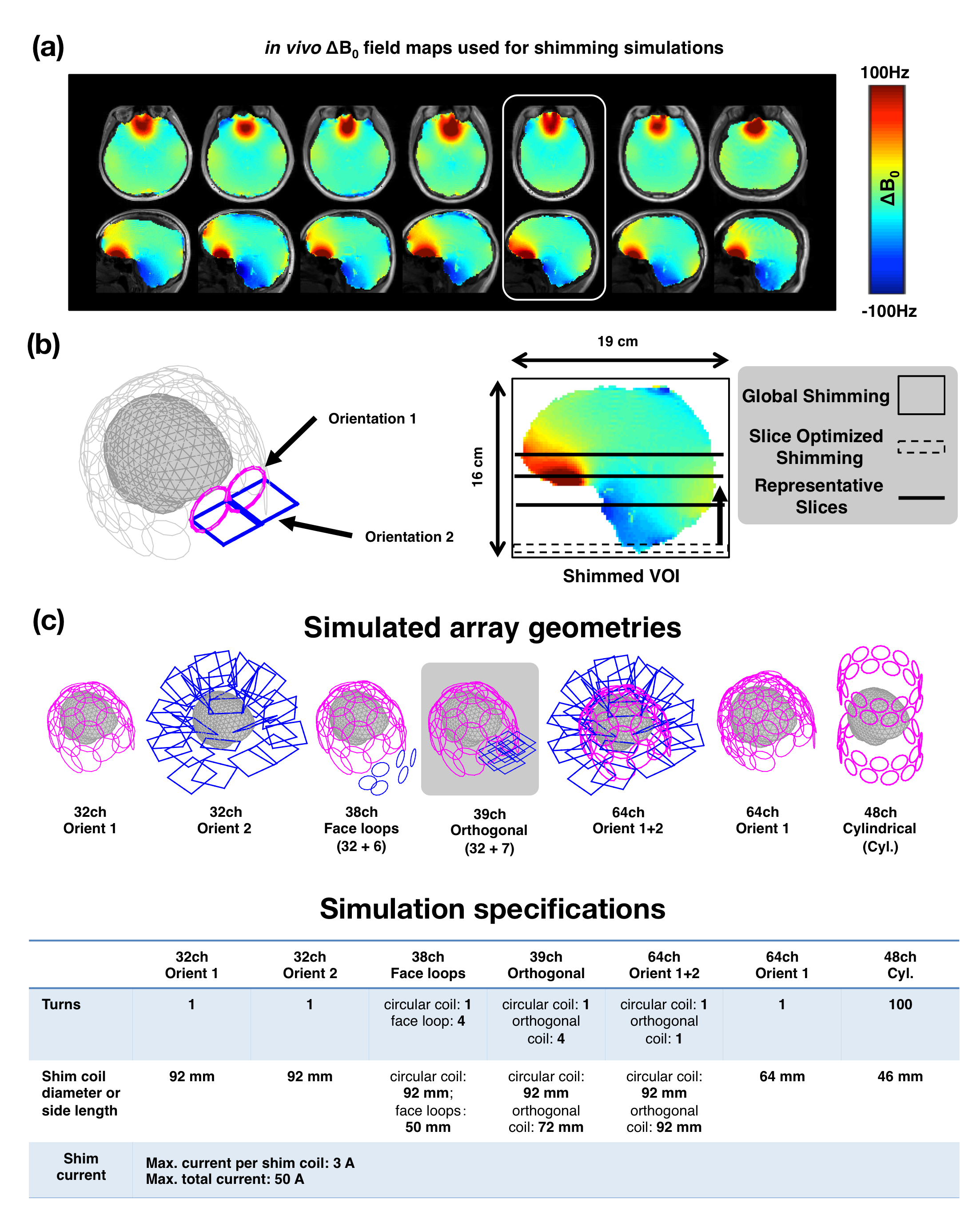
Off-resonance field maps were measured from 7 healthy subjects. We took 65 slices of dual-echo gradient echo images (2x2x2mm3 voxel; TR = 10ms; TE1 = 2.00ms; TE2 = 4.46ms; flip-angle = 15°) on a 3T scanner (Skyra, Siemens, Erlangen, Germany) after applying the system’s second-order spherical harmonic (SH) global shimming. An off-resonance field map was calculated by measuring the phase accrued between two echo times at each image voxel(4). An off-resonance field map, ΔB0 (x, y, z), was created by first unwrapping the phase at each image voxel and then registering individual’s off-resonance map to an arbitrarily selected subject (FLIRT and PRELUDE in FSL(5-7)).
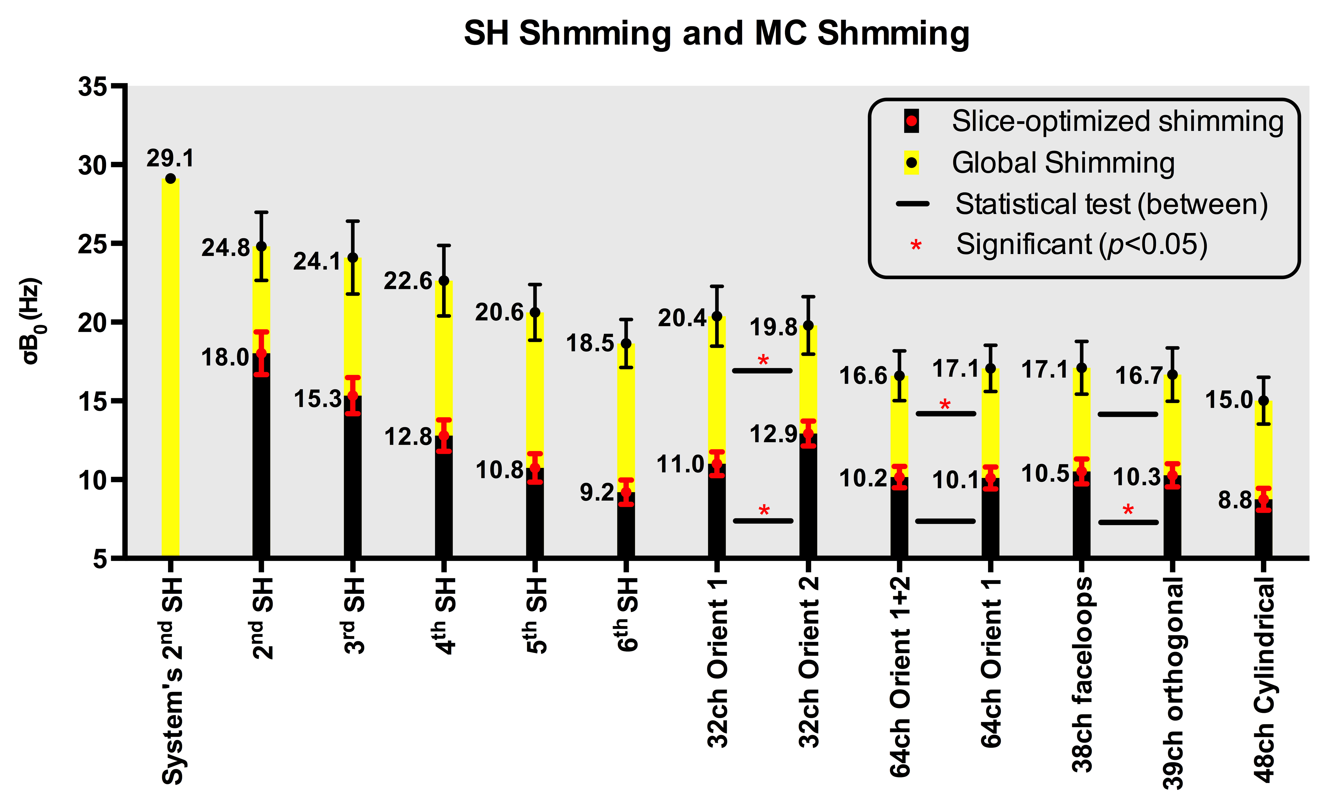
We first used simulation to evaluate how shim coils arranged in orthogonal to RF coils can improve the field inhomogeneity. The magnetic field from each shim coil was simulated by the Biot-Savart’s law. Seven different array geometries with different numbers of shim coils (between 32 and 64) were calculated. The geometries of these 7 arrays were shown in Figure 1. The standard deviation of B0 (σB0) within a brain mask was used to assess the shimming performance.
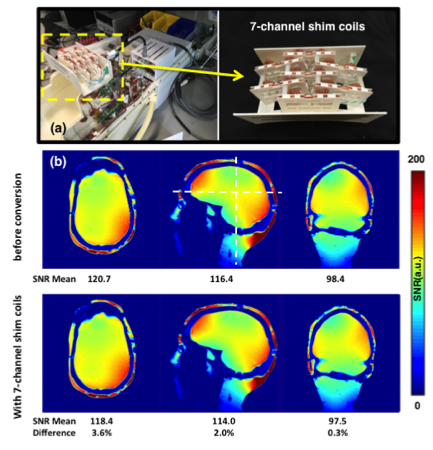
We implemented a 39-channel orthogonal RF-shim array, which included the 7 rectangular shim coils at the “brim” of a 32-channel RF-shim array(3). These 7 channel rectangular shim coils were built on the 3D-printed substrates, encircled by 4-turns of AWG22 copper wire, connected to chokes (self-shielding toroidal inductors; 32-turns, AWG22, 16mm O.D., 9mm I.D.) to isolate RF signal.
SNR maps(8) were calculated after collecting data using an anthropomorphic head phantom(9) before and after adding 7 rectangular shim coils to convert the 32-channel RF-shim array to the 39-channel orthogonal RF-shim array. Distributions of B0 caused by each shim coil were measured by supplying 300mA to each shim coil separately using a water-filled balloon phantom (diameter: 20cm). These maps were used to create a basis-set for shimming. Shim currents were supplied by a digitally-programmable, open-source current driver(10).
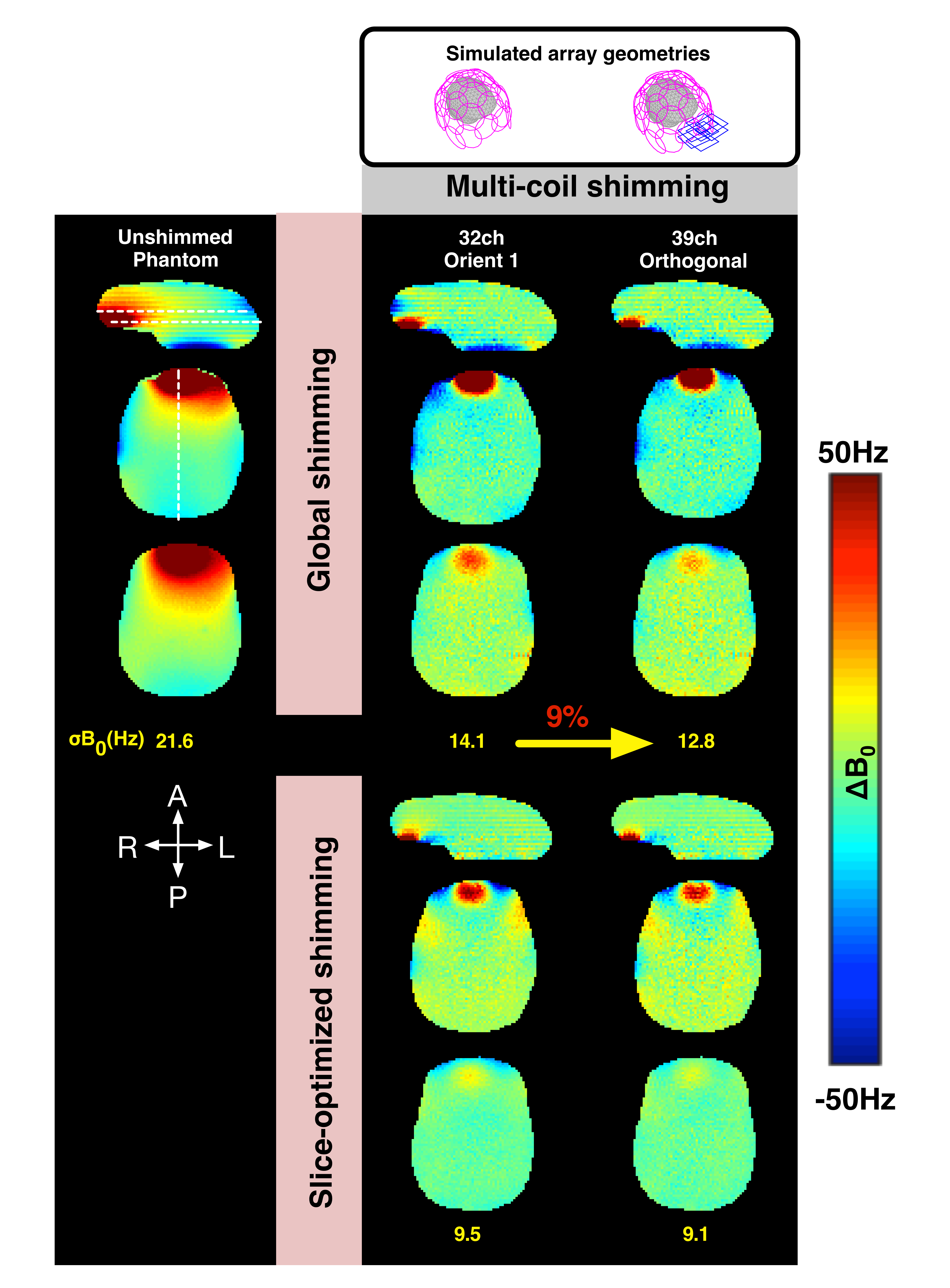
We used a head phantom with a built-in off-resonance structure to test the performance of the 39-channel orthogonal RF-shim array. A dual-echo gradient echo sequence was applied to acquire the head phantom field map. Finally, the shim coil field maps were used to predict the shimming performance under the constraints that the shim current on each shim coil should not exceed 2A and that the total shim current across all shim coils should not exceed 20A. Global shimming and slice-optimized shimming were numerically simulated based on empirically derived field maps.
Result
Figure 2 summarizes the performance of shimming across 7 subjects after various shimming approaches. Compared to the 2nd SH shimming over the whole head (σB0 = 29.1Hz), restricting the volume-of-interest of the 2nd SH shimming within the brain reduced σB0 to 24.8Hz. Figure 3a shows the 32-channel RF-shim array(3) and the 7-channel shim coil array. Comparing the SNR maps of 32-channel RF-shim array (Figure 3b), there was marginal SNR loss after adding the 7-channel shim array and its connecting wires. Figure 4 shows the ΔB0 maps measured with a balloon phantom. Each shim coil produced as strong as 300Hz resonance frequency shift near the edge of the phantom. Figure 5 shows the ΔB0 field maps in global and slice-optimized shimming using the 32-channel RF-shim array and 39-channel orthogonal RF-shim arrays.Discussion
We propose to place local shim coils such their coil plane is perpendicular to the nearby RF receiver coil plane in order to minimize the coupling and thus SNR degradation. Better global shimming can be obtained by adding 7 orthogonal shim coils (Figures 2 and 5) with marginal SNR loss (Figure 3). Further applications of in structural, functional, and metabolic brain imaging as well as spectroscopy are on the way.Acknowledgements
This work was supported by DFG SCHE658/13 and the Max Planck Society. This work was partially supported by Ministry of Science and Technology, Taiwan (103-2628-B-002-002-MY3, 105-2221-E-002-104), and the Academy of Finland (No. 298131).References
1. Juchem C, Nixon T W, McIntyre S, et al. Magnetic field modeling with a set of individual localized coils. J Magn Reson, 2010, 204(2): 281-289
2. Truong TK, Darnell D, Song AW. Integrated RF/shim coil array for parallel reception and localized B0 shimming in the human brain. NeuroImage 2014;103:235-240
3. Stockmann, J. P., Witzel, T., Keil, B., Polimeni, J. R., Mareyam, A., LaPierre, C., Setsompop, K. and Wald, L. L., “A 32-channel combined RF and B0 shim array for 3T brain imaging”, Magn Reson Med 2016; 77(1): 441–451
4. Irarrazabal P, Meyer CH, Nishimura DG, Macovski A. Inhomogeneity correction using an estimated linear field map. Magn Reson Med 1996;35(2):278-282
5. Smith SM, Jenkinson M, Woolrich MW, Beckmann CF, Behrens TEJ, Johansen-Berg H, Bannister PR, De Luca M, Drobnjak I, Flitney DE, et al. Advances in functional and structural MR image analysis and implementation as FSL. Neuroimage 2004;23:S208–S219.
6. Jenkinson M, Bannister P, Brady M, Smith S. Improved Optimization for the Robust and Accurate Linear Registration and Motion Correction of Brain Images. NeuroImage 2002;17(2):825-841
7. Smith SM. Fast robust automated brain extraction. Hum Brain Mapp 2002;17:143–155.
8. Kellman P and McVeigh ER. Image reconstruction in SNR units: a general method for SNR measurement. Magn Reson Med. 2005;54(6):1439-47
9. Guerin B, Stockmann JP, Baboli M, Torrado-Carvajal A, Stenger AV, Wald LL. Robust time-shifted spoke pulse design in the presence of large B0 variations with simultaneous reduction of through-plane dephasing, B1+ effects, and the specific absorption rate using parallel transmission. Magn Reson Med. 2016;76(2):540-54
10. Arango N, Stockmann JP, Witzel T, Wald LL. Open-source, low-cost, flexible, current feedback-controlled driver circuit for local B0 shim coils and other applications. ISMRM 2016, p. 1157
Figures