0650
Actively-tracked metallic electrophysiology catheters and guidewires with miniature floating radio-frequency traps: Theory, Design and Validation1Cardiology, Johns Hopkins University, Baltimore, MD, United States, 2Radiology, Stanford University, Stanford, CA, United States, 3Radiology, Cincinnati Children's Hospital Medical Center, Cincinnati, OH, United States, 4Abbott Inc., Saint Paul, MN, United States
Synopsis
Metal-reinforced catheters have improved steerability and pushability. Currently, long (>wavelength/8) metallic-braided or metallic-tube-reinforced active MRI-compatible devices do not exist, due to risks of heating of surrounding tissue. Metallic-backbone devices may be possible if heating-sources are attenuated. Concentric-tube RF traps were miniaturized (“MBaluns)” by using leaky (loosely-wound) solenoids in-place of the external tube, providing transverse magnetic fields to attenuate (a) surface electric-fields on metals and (b) common-mode propagation on internal-cables. We validated (1) a 1.1mm outer-diameter (OD) active metallic-tube-based guidewire and (2) a 2.6mm OD metallic-braid-based electrophysiology catheter via; Electromagnetic modeling, Network-Analyzer electrical tests, phantom imaging and navigation into swine hearts.
Introduction
Invasive deflectable cardio-vascular devices (sheathes, catheters, guidewires) frequently incorporate metallic tubes/rods or are reinforced with metallic braids. Metals’ mechanical properties provide for reduced kinking, better steerability, improved pushability and torque transmission, allowing for remote manipulation of lengthy (L>1000mm) small external-outer-diameter (ODE<3mm) structures. However, current MRI-compatible devices contain only short lengths (<λ/8, where λ is wavelength) of metal1 , reducing body-coil-induced Radio-Frequency (RF) surface electrical (E) currents on the metal, which can heat surrounding tissues. Additionally, switched RF fields and gradients create transient magnetic (M) fields on lengthy metals1,2 leading to undesirable B0 inhomogeneity and B1 hyperintensity. Without metallic support, MRI-compatible catheters are generally larger, or have inferior maneuverability. Passive guidewires can be constructed of bisected metal rods, but are hard to visualize2. Active MRI catheters have sensors on their distal shaft (MR-tracking micro-coils, ECG/impedance-tracking electrodes), resulting in multiple electrical cables running up the catheter shaft. Without external (metallic) conductive shielding, the cables receive body-coil-induced common-mode currents, and require individual heat-amelioration solutions3, taking-up considerable space, and possibly attenuating desired (differential-mode) signals.
The goal was development and testing of MRI-compatible Electrophysiology devices with full-length metallic-braid or metallic-tube shafts. Periodic miniature resonant RF-traps (MBaluns) were placed on the metals, intended to suppress surface currents on the metal and common-mode currents on internal cables.
Methods
Methodology: MRI receiver-coil assemblies, enclosing multiple cables, are overlaid with a conductive-shield and periodic “floating” (non-contacting) resonant RF traps (Baluns) which attenuate common-mode currents in the cables and shield. Baluns are constructed of elongated (~10 cm) internal and external concentric copper tubes, separated by a dielectric layer (ε) and shorted at one end, producing a transverse magnetic field (Mt). The Balun’s inductance is resonated at the Larmor frequency with a parallel-capacitor.
Active-Catheter Design: If Baluns are reduced in diameter, reasonable-length concentric tubes cannot generate sufficient inductance. To compensate, we replaced the external tube with a leaky solenoid, where large inter-winding distances (∆), relative to the wire diameter (l), and the large (N>50) number of windings, generate a large Mt and inductance. The internal Balun tube was replaced by a non-ferrous conductive braid, since the braid’s woven structure does not support large surface E currents. The leaky solenoids were soldered to the braid, and resonated with miniature capacitors (MBaluns), attenuating common-mode currents on cables within the braid, and residual E fields on the braid surface. Figure 1 shows finite-difference Electromagnetic simulation of an MBalun placed off-center within and irradiated by a “Bird-Cage” body-coil, showing a large confined Mt field between the two surfaces.
Active-Guidewire Design: For larger form factors (L/ODE) and larger stiffnesses, a solid internal tube was required. Periodic high-conductivity metal coatings were added to the tube underneath the MBaluns, with surface-wave impedances4 Z=(1+j)/δϬ, where δ is the skin depth and Ϭ is the conductivity, which differ from the tube’s, providing for strong surface reflections, and thereby only sustaining higher-frequency fields4,5.
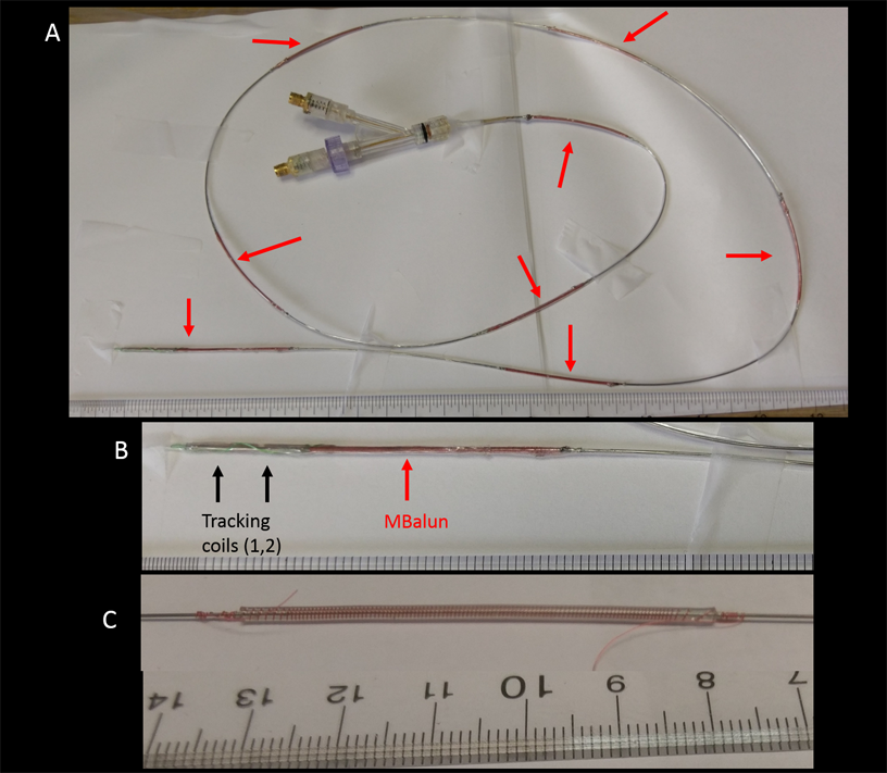
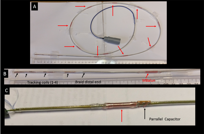
Devices Constructed: (1) Active guidewire with backbone of OD=0.5mm nitinol tube (Fig. 2) L=1170mm, ODE=1.1mm, 2 multilayer MR-Tracking coils at the distal end6, 48AWG coax. MBalun-design1; 50mm-length/MBalun, N=150, ∆=0.3mm, l=0.1mm, ε thickness=0.2mm,8 MBaluns/guidewire (2) Irrigated Electrophysiology catheter with backbone of OD=1.9mm tinned-copper braid (Fig. 3) L=1000mm, ODE=2.6mm, 4 MR-Tracking coils6 at distal end, 42AWG coax. MBalun-design2; 15mm-length/MBalun, N=50, ∆=0.3mm, l=0.1mm, ε thickness=0.2mm, 9 MBaluns/catheter. MBaluns were resonated at 63.8 MHz with 0.5mm thick capacitors.
Network-Analyzer (NA) RF tests: Signals on coaxial cables; (a) minimal desired-signal (differential-mode) attenuation; (b) large induced-signal (common-mode) attenuation. Currents on metallic braids and tubes; (c) large attenuation of induced signal. Common-mode signals were induced onto cables, braids, and tubes using large transmit-coils. Control tests performed on devices without MBaluns.
MRI large-phantom (150x30cm2) High-SAR tests: Single-shot scans; (a) minimal-TR 900 flip-angle Steady-State-Free-Precession (SSFP); (b) 1800 flip-angle (ETL=256) Fast-Spin-Echo. Signal-hyper-intensity around shafts was investigated.
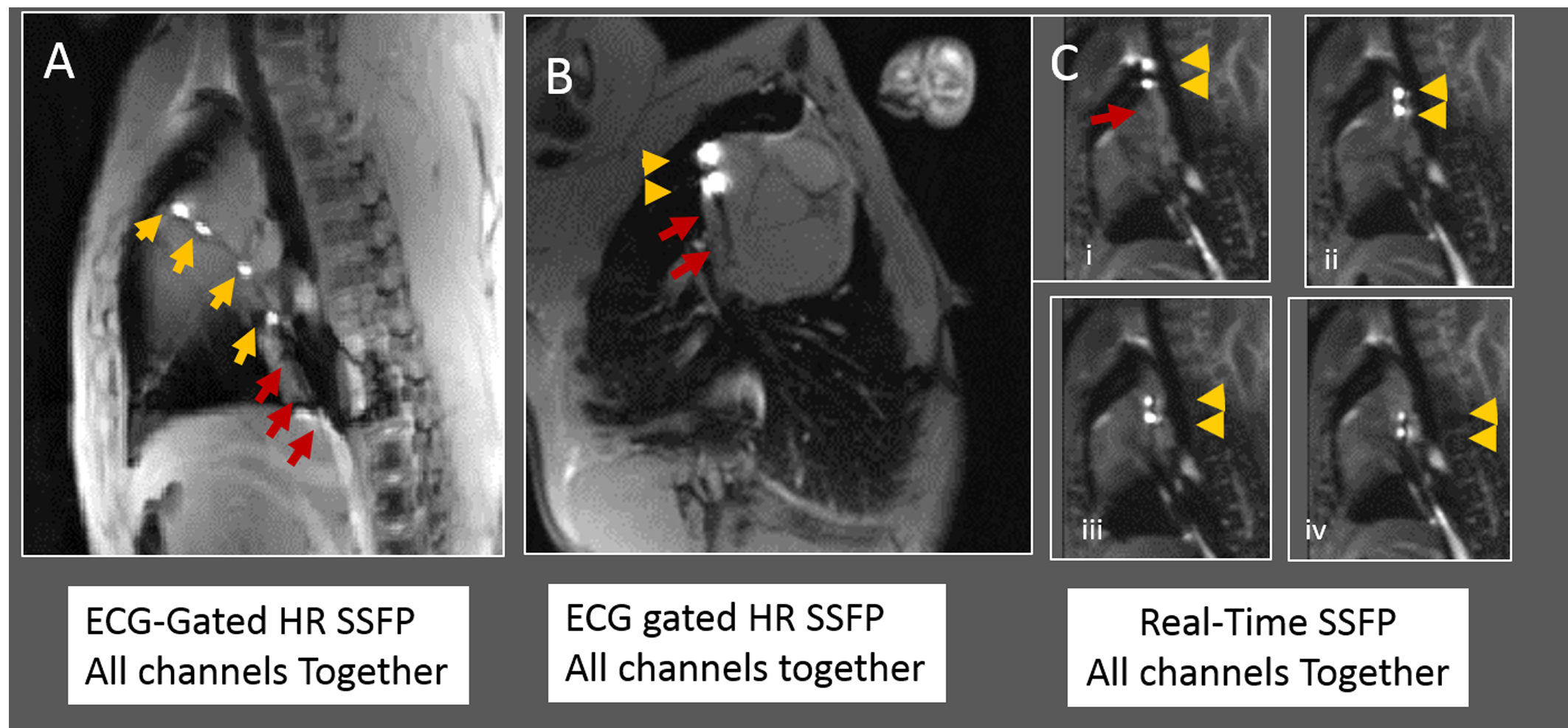
MRI Swine tests: Both devices were navigated into swine right atriums in a Siemens Avanto. Abdominal and spine-arrays were used, along with dedicated MR-tracking receivers. Imaging: Real-time SSFP and ECG-gated high-resolution SSFP.
Results
Network Analyzer: Cable differential-mode signals were not (+0.2dB) attenuated. Common-mode signals on cables were attenuated by (1) 15dB/Balun and (2) 8 dB/Balun, respectively. Surface-waves on metallic-tubes or metallic-braid were attenuated by 15dB/MBalun and 9dB/MBalun, respectively.
MRI large-phantom High-SAR tests: No (+5degree) flip-angle increase was observed around shafts. Appearance was of a dark shaft, with hyper-intense distal MR-Tracking coils.
MRI Swine navigation: MR-Tracking coils were well visualized inside heart (Fig. 4, 5). Device shafts were completely dark, validating MBalun effectiveness. Active-guidewire manipulation was easy.
Conclusions
A construct of MRI-compatible active catheters with metallic backbones was validated. It improves steerability, mitigates heating, and allows reducing device cross-section.Acknowledgements
NIH R01-HL094610References
1. Kocaturk O, Saikus CE, Guttman MA, et al. Whole shaft visibility and mechanical performance for active MR catheters using copper-nitinol braided polymer tubes. J Cardiovasc. Magn. Reson. 2009, 11: 29;1-20..
2. Basar B, Rogers T, Ratnayaka K, et al. Segmented nitinol guidewires with stiffness-matched connectors for cardiovascular magnetic resonance catheterization: preserved mechanical performance and freedom from heating. J Cardiovasc. Magn. Reson. 2015; 30: 105-115.
3. Weiss S, Wirtz D, David B, et al. In vivo evaluation and proof of radiofrequency safety of a novel diagnostic MR-electrophysiology catheter. Magn. Reson. Med. 2011; 65: 770–777.
4. Sievenpiper D, Zhang L, Broas RFJ, et al. High-Impedance Electromagnetic Surfaces with a Forbidden Frequency Band. IEEE Trans. Microwave Theory and Techniques 1999; 47: 2059-2074
5. Elachi C, Waves in active and passive periodic structures: A review. Proc. IEEE 1976; 64: 1666–1698
6. Wang W, Dumoulin CL, Viswanathan AN, et al. Real-time active MR-tracking of metallic stylets in MR-guided radiation therapy. Mag. Reson. Med. 2015; 73: 1803-11.
Figures