0648
A Reproducible and Lower-Cost Thermo-Acoustic Ultrasound System for Detection of RF-Induced Lead Tip Heating in MRI1Electrical Engineering, Stanford University, Stanford, CA, United States, 2Procyon Engineering, San Jose, CA, United States
Synopsis
Thermo-acoustic ultrasound (TAUS) has been shown to be able to detect the peaks in local SAR indicative of RF-induced lead tip heating in an MRI setting. Here, we detail a reproducible TAUS acquisition system consisting entirely of commercially accessible electronics that can interface with an MRI scanner. This system achieves comparable performance to our previously demonstrated acquisition system with lower cost electronics, while also providing additional functionality that could aid in the development of a robust TAUS pre-scan to assess the risk of RF-induced lead tip heating in MRI.
Purpose
Coupling between MRI transmit coils and the leads of implanted medical devices can cause dangerous RF-induced heating near the device lead tips,1,2 preventing device recipients from receiving MRI scans due to uncertainty regarding whether excessive heating will occur.3 A non-invasive pre-scan procedure to assess the risk of RF-induced heating could allow many more patients to be scanned.
As demonstrated in prior work,4-7 thermo-acoustic ultrasound (TAUS) is a promising technique for identifying peaks in local SAR near lead tips that result in RF-induced heating, and a TAUS acquisition system can be integrated with MRI scanner electronics for a TAUS pre-scan. Here, we demonstrate a TAUS system consisting of lower cost and commercially accessible electronics, allowing for a reproducible setup that also provides additional functionality over the previously demonstrated system.
Methods
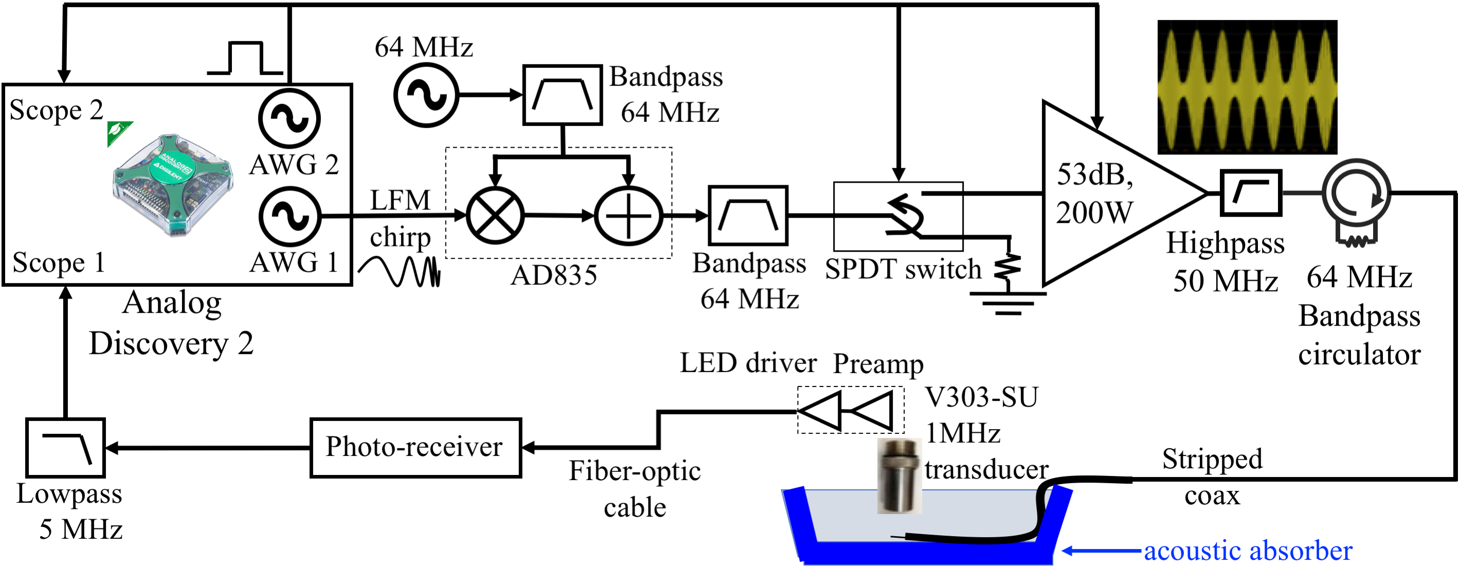
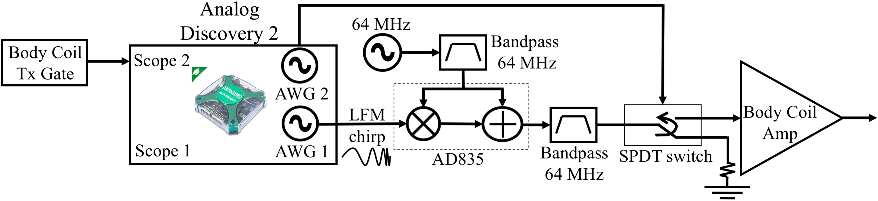
Our original TAUS system uses a Medusa MRI console8 to transmit and receive. In fact, synchronous transmit and receive for TAUS acquisitions can also be performed using a digital oscilloscope with arbitrary waveform generator (AWG) outputs. Here we use the two AWG outputs and the two oscilloscope channels of an Analog Discovery 2 (AD2) (Digilent,Pullman,WA,USA), a multi-functionality device with 14-bit ADCs and a USB interface, to perform frequency-modulated continuous-wave (FMCW) TAUS acquisitions7 with the setup diagrammed in Figure 1.
To generate the transmit waveform for FMCW amplitude modulation, one AWG output generates a linear frequency modulation (LFM) chirp signal that amplitude modulates an RF carrier. The other AWG output transmits a binary logic signal that is high during the chirp signal transmit. This logic signal activates an SPDT switch routing the transmit signal to an RF power amplifier driving the desired transmit element, controls the external gating input on this power amplifier, and drives one oscilloscope channel on the AD2 to trigger scope acquisitions.
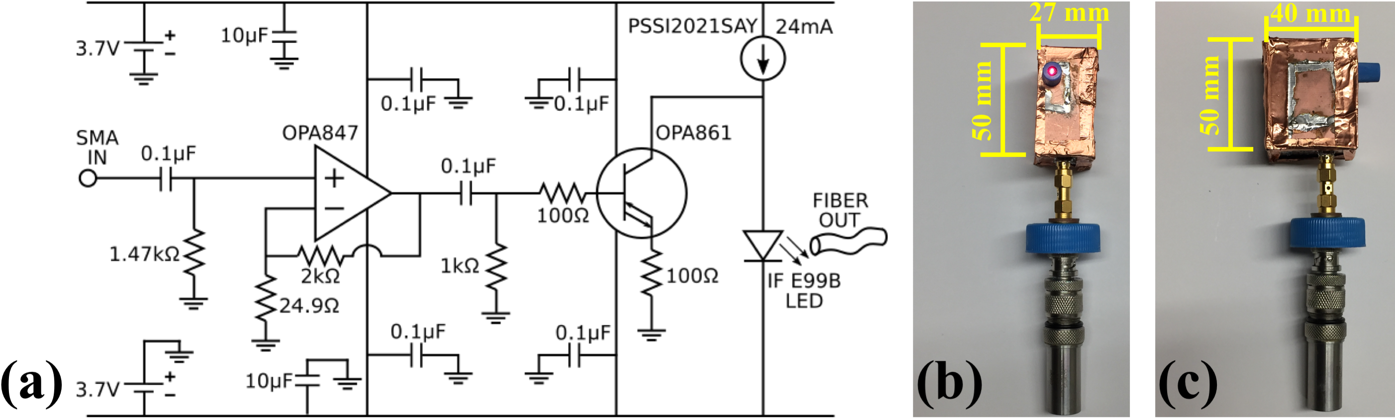
In the receive chain, a shielded box containing a custom-built preamplifier and LED driver powered by two nonmagnetic 3.7V batteries (Figure 2) is attached to the ultrasonic transducer used to detect the thermo-acoustic signal. The LED driver is optically coupled to a photo-receiver, whose output is low-pass filtered and connected to an oscilloscope channel on the AD2.
To evaluate the ability of this TAUS system to detect the thermo-acoustic signal near a lead tip, the transmit chain directly drove a stripped coaxial cable whose exposed conductor was immersed in saline solution, and a 1MHz Olympus V303-SU ultrasonic transducer was used to detect the excited signal, as indicated in Figure 1. Separate TAUS acquisitions were performed using the system described here with an AD2 and the one described previously5,7 that uses the Medusa console. The acquisitions averaged 100 measurements, which each used a 400µs LFM chirp with a 1MHz center frequency for amplitude modulating a 64MHz carrier. The chirp bandwidth was set to 375kHz for the acquisitions using the Medusa setup, whose maximum transmit and receive bandwidth is 500kHz. Due to the larger bandwidth of the AD2, acquisitions using different chirp bandwidths (375kHz, 500kHz, 750kHz, and 1MHz) were compared using that setup.
Results
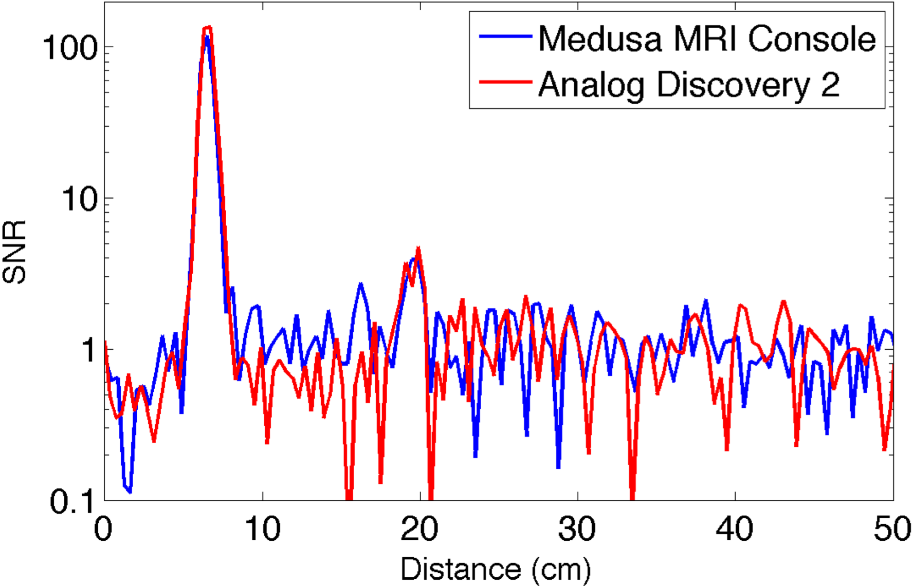
Figure 3 shows plots of the SNR versus range for the TAUS systems using the Medusa console and the AD2. The similarity between the two plots shows that both systems performed comparably.
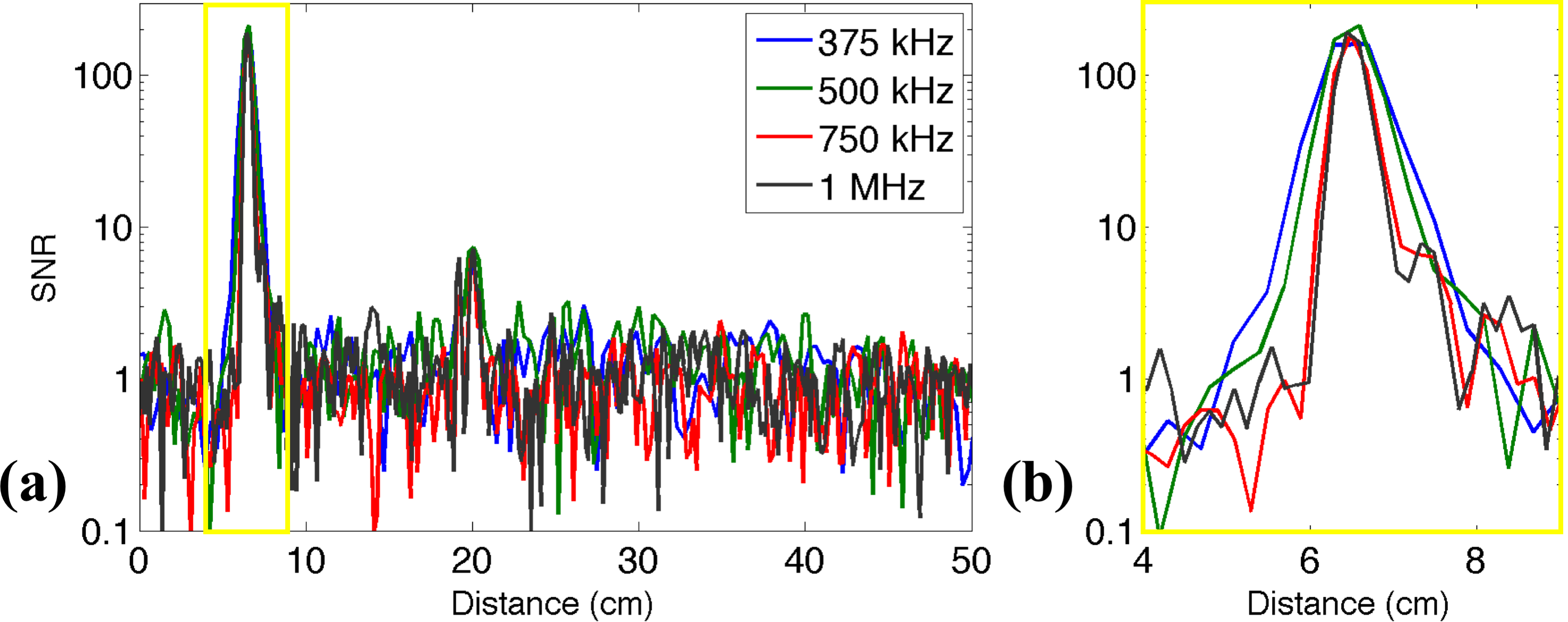
Figure 4 shows the SNR versus range when using the AD2 for acquisitions with different bandwidths. The SNR is similar for the different cases, and the spatial resolution improves as the bandwidth increases. However, the resolution improvements become minimal as the TAUS acquisition bandwidth exceeds the transducer bandwidth.
Discussion
Unlike the Medusa console, digital oscilloscopes do not digitally demodulate the received signal, requiring a higher sampling frequency to avoid aliasing. For the AD2, the limited buffer sizes of the oscilloscope and AWG channels also create a tradeoff between the acquisition duration and the sampling frequency. Nonetheless, with the high availability of programmable digital oscilloscopes, this approach improves the reproducibility of the TAUS system and may facilitate scaling to a system with multiple acoustic receivers. Additionally, the greater transmit and receive bandwidth allow for higher bandwidth acquisitions, a key for a more robust TAUS pre-scan.7
As done previously with the Medusa-based system,5,7 the TAUS system with the AD2 should be able to interface with an MRI scanner to transmit the custom RF waveforms used for TAUS acquisitions to MRI transmit coils (Figure 5), allowing characterization of the lead tip SAR from these coils.
Conclusion
We have developed a TAUS acquisition system, consisting entirely of easily accessible electronics, capable of detecting the peaks in lead tip SAR associated with RF-induced lead tip heating.Acknowledgements
This work was supported by the NIH under grants R01EB008108 and P01CA159992, the Department of Defense (DoD) through the National Defense Science & Engineering Graduate Fellowship (NDSEG) program, and the William R. Hewlett Stanford Graduate Fellowship.References
1. Nitz WR, Oppelt A, Renz W, Manke C, Lenhart M, Link J. On the heating of linear conductive structures as guide wires and catheters in interventional MRI. J Magn Reson Imaging. 2001;13(1):105-114.
2. Nyenhuis JA, Park S-M, Kamondetdacha R, Amjad A, Shellock FG, Rezai AR. MRI and implanted medical devices: basic interactions with an emphasis on heating. IEEE Trans Device Mater Rel. 2005;5(3):467-480.
3. Kalin R, Stanton MS. Current clinical issues for MRI scanning of pacemaker and defibrillator patients. Pacing Clin Electrophysiol. 2005;28(4):326-328.
4. Scott G, Etezadi-Amoli M, Stang P, Nan H, Aliroteh M, Arbabian A, Pauly J. Thermo-acoustic ultrasound detection of RF coil and tip SAR. Proc Intl Soc Mag Reson Med. 2015;23:377.
5. Dixit N, Stang P, Pauly J, Scott G. Thermo-acoustic ultrasound detection of RF tip heating in MRI. Proc Intl Soc Mag Reson Med. 2016;24:349.
6. Dixit N, Stang P, Pauly J, Scott G. FDTD simulation of thermo-acoustic ultrasound for detection of RF tip heating. Proc Intl Soc Mag Reson Med. 2017;25:483.
7. Dixit N, Stang PP, Pauly JM, Scott GC. Thermo-acoustic ultrasound for detection of RF-induced device lead heating in MRI. IEEE Trans Med Imaging. in press; doi:10.1109/TMI.2017.2764425.
8. Stang PP, Conolly SM, Santos JM, Pauly JM, Scott GC. Medusa: a scalable MR console using USB. IEEE Trans Med Imaging. 2012;31(2):370-379.
Figures