0645
Experimental implementation of test-field diversity method for RF-induced heating assessment of medical implants1IT'IS Foundation, Zurich, Switzerland, 2ETH-Zurich, Zurich, Switzerland
Synopsis
We summarize the experimental implementation of test-field diversity (TFD) method for radiated immunity testing of medical implants. The TFD method is used to provide a diverse and well-characterized incident conditions to the implant during radiated immunity test. As an illustrative example, the TFD is used for in vitro validation of a Tier 3 model that describes RF-induced heating of a commercial medical implant at 64 MHz. Results shown a dynamic range of 10 dB for the tip deposited power can be obtained experimentally. The experimental instrumentation and the practical considerations of the method are discussed.
Introduction
Experimental radiated immunity test is an integral part of implant modeling as it is often needed for the validation of an implant model. Radiated immunity test generally comprises a TSM-filled test phantom where the implant is submerged and an RF exposure source. For leaded implants, the RF-induced heating is dominated by the coupling of the implant with the tangential component of the electric fields along its length, $$$E_\textrm{tan}$$$. Usage of different combinations of phantoms and implant routings is commonly exploited as a vehicle to achieve diversity in $$$E_\textrm{tan}$$$ along leaded implants1. In practice, the manipulation of implant routings is limited by the finite size of the test phantoms; one must carefully determine the influence of truncated boundaries and lead segments scattering as they may have appreciable influence on the RF-heating results we aim to assess2.
We have recently reported the theoretical feasibility of a testing method by which more than 1K exposure conditions to the implants were achieved and a dynamic range of more than 30 dB of total dissipated lead tip power were obtained3. In this work, we describe the practical implementation of the test-field diversity (TFD) experimental method where diversity in the test field conditions is achieved by utilizing only limited combination of test phantom and implant routings. Practical considerations of the experimental design is also discussed.
Method
The implementation of TFD method for the validation of a Tier-3 (T3) implant model at 64 MHz is described. As an illustrative example, we applied the method to a commercial 70-cm AIMD.
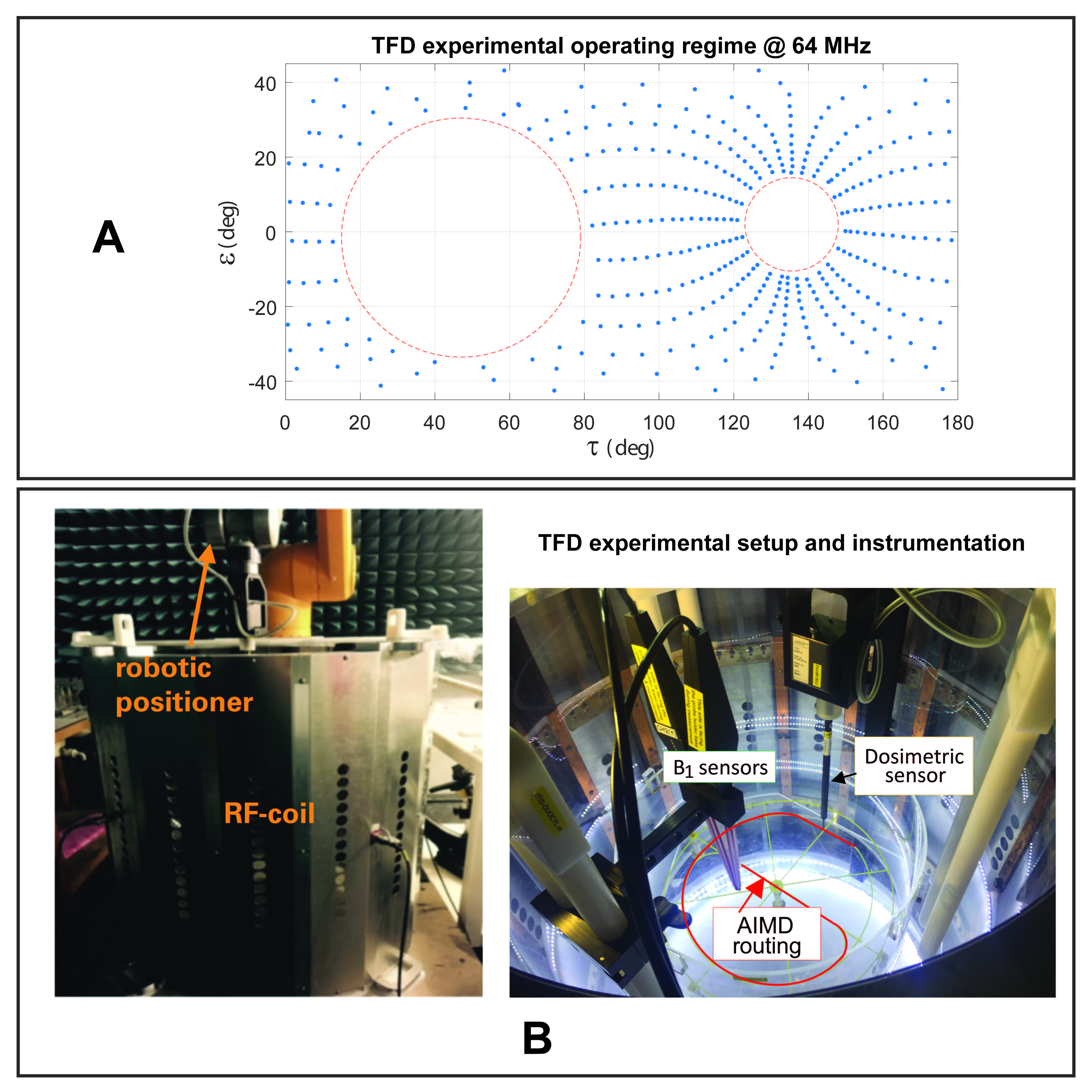
The experimental setup comprises a generic shielded RF-birdcage coil with 65-cm rungs and 75-cm diameter. The test phantom is an iso-symmetrically loaded cylindrical phantom with 22-cm diameter, filled with tissue-simulating medium (εr = 78, σ = 0.47 S/m) to a fill-height of ±10cm about the iso-center of the coil. Six implant routings are designed to accommodate testing of leaded implants with lengths between 30-cm to 110-cm. RF-induced local deposition at the lead tip is measured with a dosimetric sensor controlled by a robotic positioning arm. The exposure is characterized by optical B1 sensors, placed within the phantom. Figure 1 illustrates the experimental setup and instrumentation.
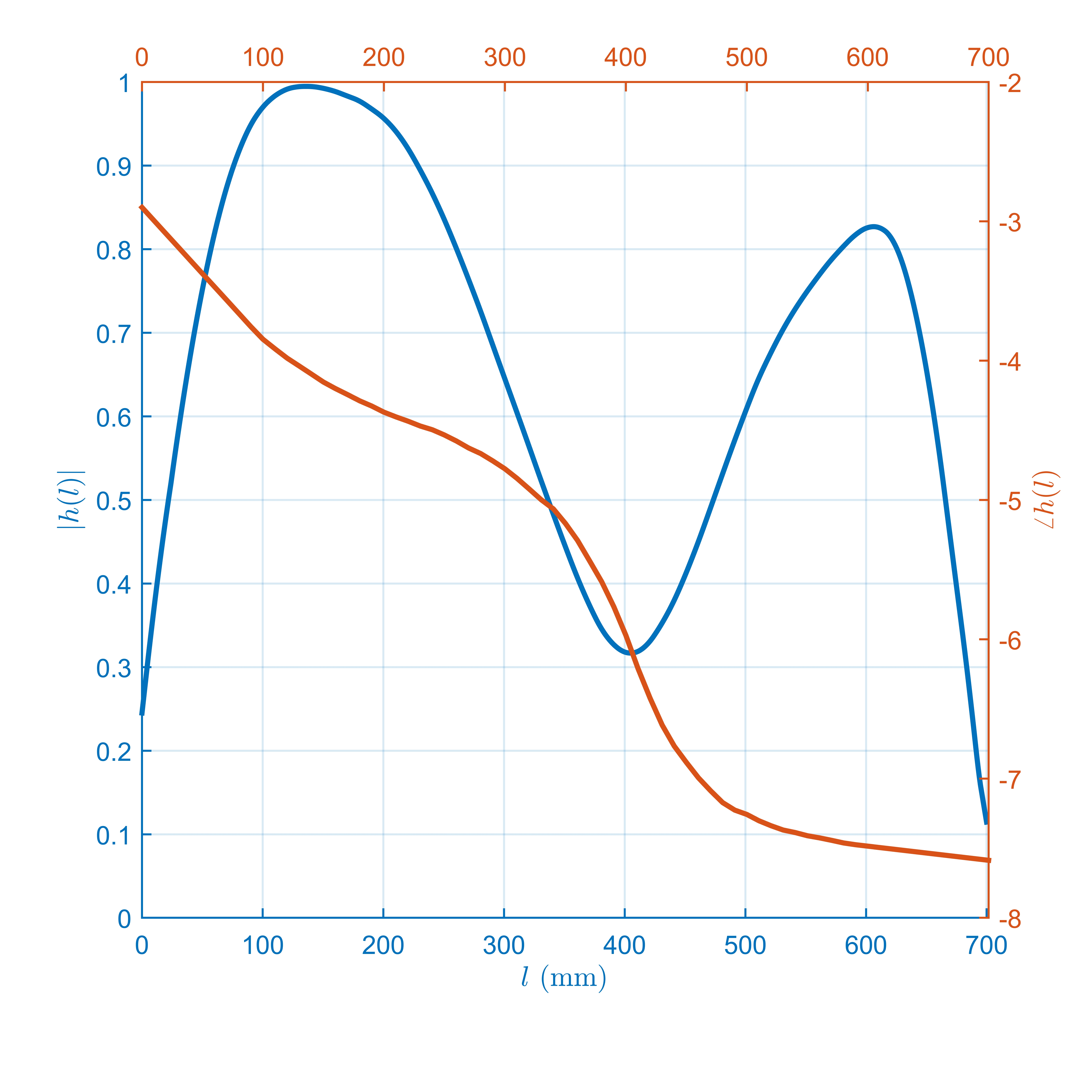
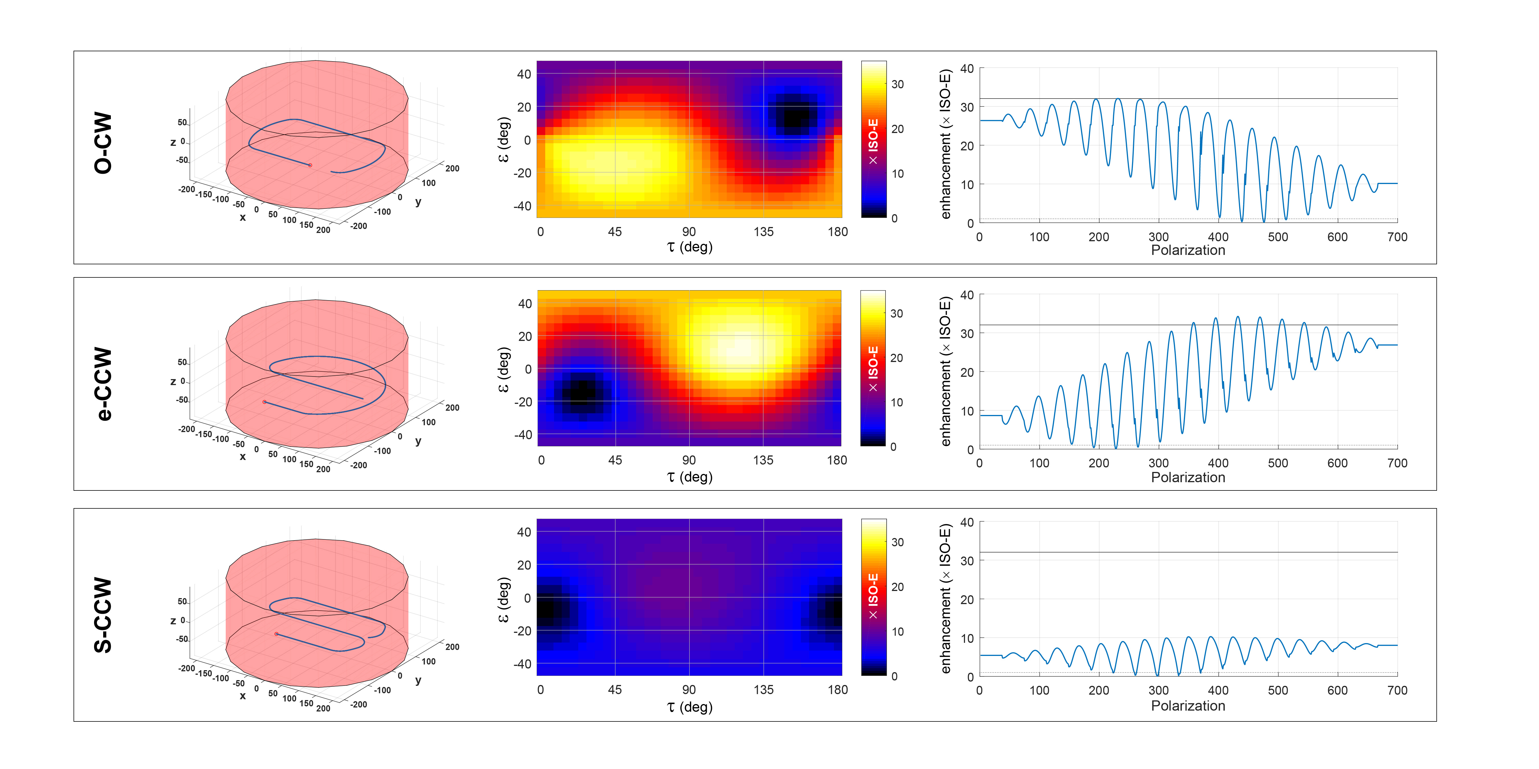
Figure 2 depicts the T3 model of the AIMD4. RF-heating of the AIMD under the different B1 exposures are emulated from the numerically model of the test setup and the T3 model. The RF-heating prediction is obtained for the different implant routings. Figure 3 illustrates the RF-heating prediction (shown as enhancement factor of the deposition at the lead tip from deposition under iso-electric exposure) as a function of B1 exposures (shown as planar projection of the Poincare′ sphere). Three (of 6) possible routings are illustrated.
In practice, only some polarization states of the B1 can be achieved by the RF exposure system. We have identified the operating regime of our exposure system which is shown in Figure 1A. Next, B1 exposures that are experimentally feasible are selected; the selection is done to maximize the dynamic range of the RF-heating of the AIMD under test. From Figure 3, we anticipate approximately 15 dB dynamic range of RF-heating (~30 folds). We assessed the standard uncertainty budget of the TFD method to be 2 dB (k = 1).
Results
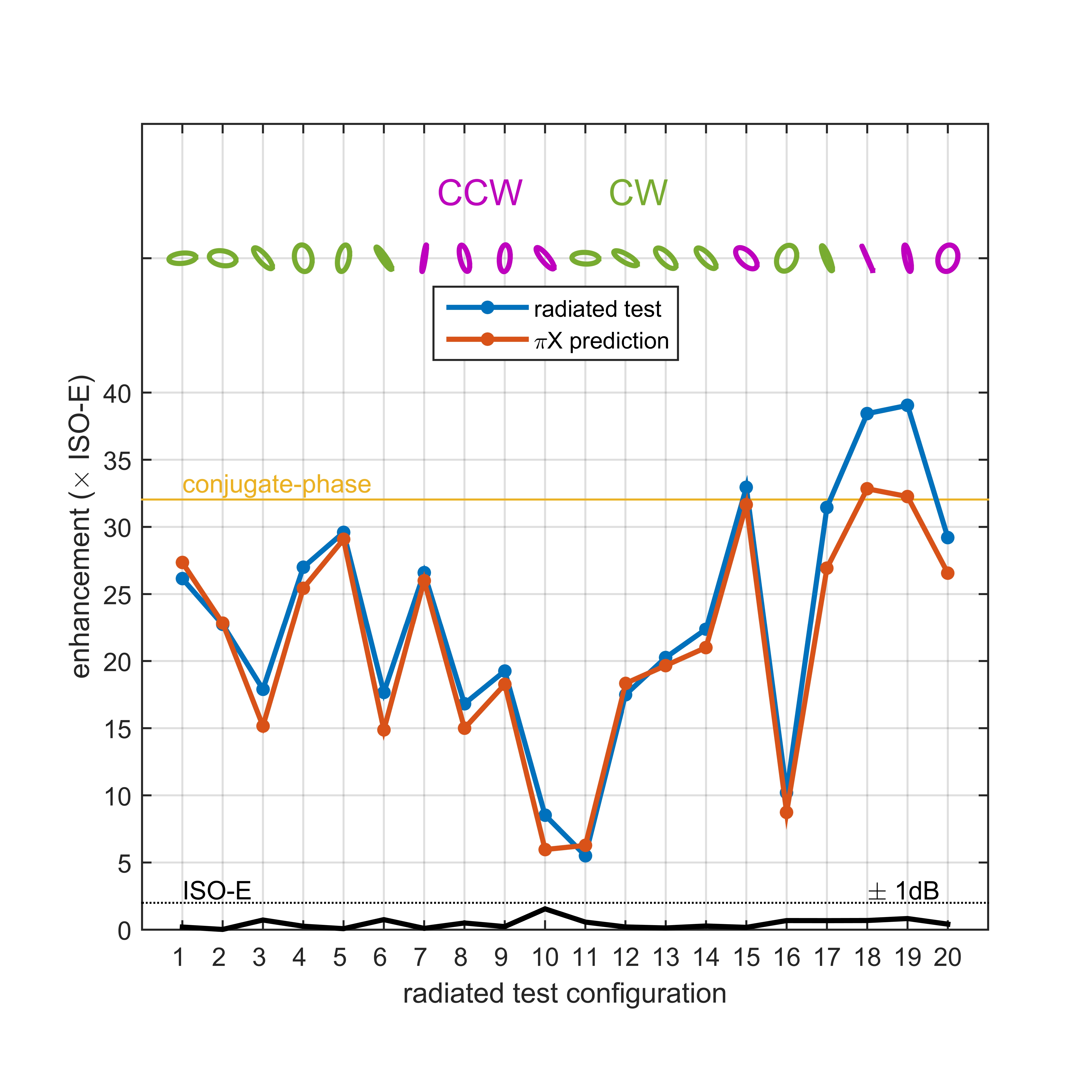
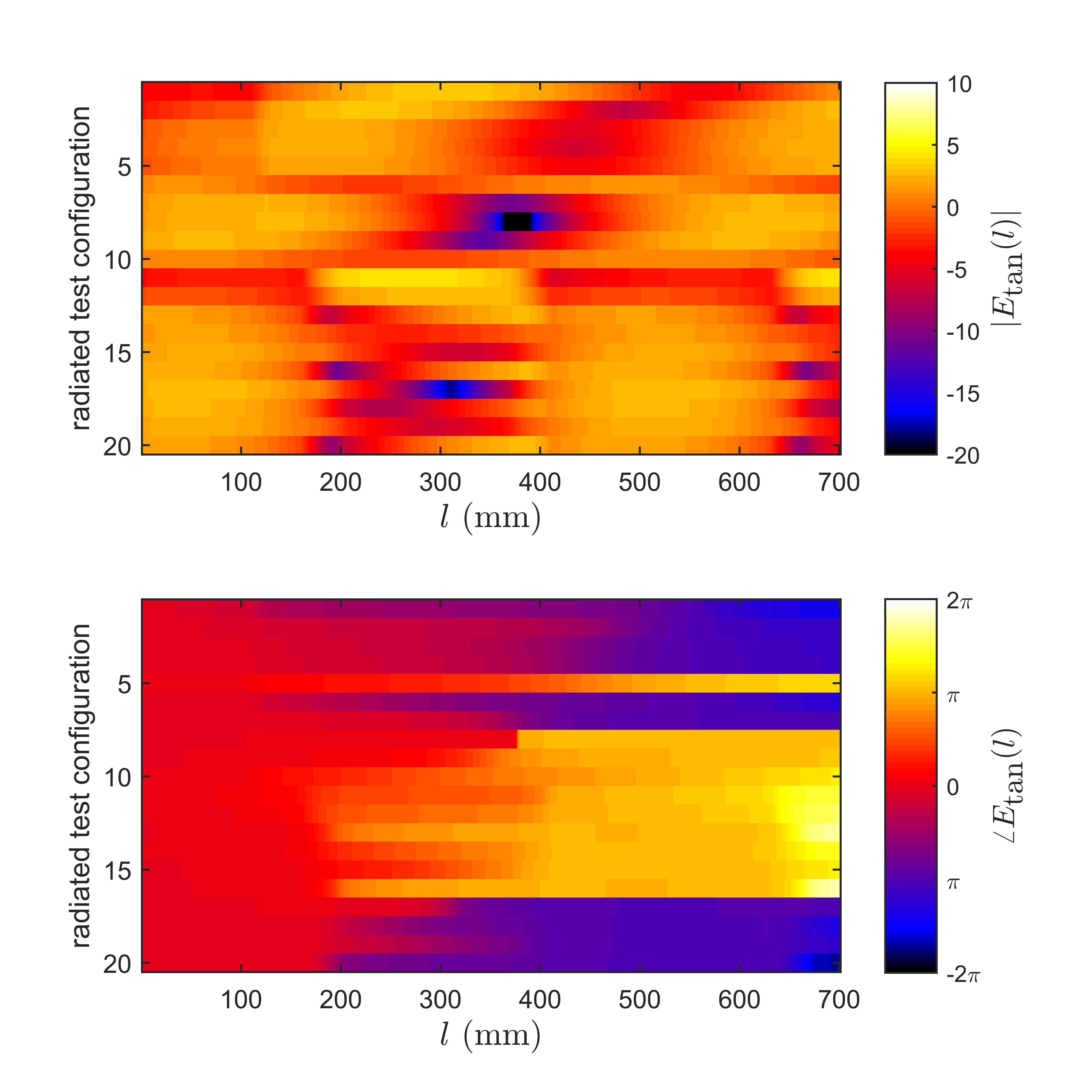
Twenty unique B1 exposures were identified to provide diverse incident conditions to the AIMD under test. Figure 4 illustrates the experimental validation of the T3 model obtained with the TFD method. As it is difficult to determine the diversity of $$$E_\textrm{tan}$$$, we can only infer the diversity of the AIMD incident condition from the dynamic range of local deposited lead tip power. Nevertheless, the characteristics of $$$E_\textrm{tan}$$$ associated with the 20 selected exposures are provided in Figure 5. The dynamic range of the tip deposition obtained from the 20 selected exposures is approximately 10 dB. The deviation between the TFD radiated tests and the T3 model prediction is within 2 dB, within the uncertainty of the TFD method.
Conclusions
In the past, usage of different combinations of phantoms and implant routings was the only available means of achieving the diversity in $$$E_\textrm{tan}$$$. Here, we have demonstrated the experimental feasibility of alternative testing method by which the combination of phantoms and routings can be kept to a minimum. Each AIMD routing is designed to minimize the effect from phantom truncated boundaries and lead segment scattering by maintaining at least 6 cm spacing to any truncated boundaries and at least 10 cm spacing between adjacent parallel lead segments. With the trade-off of increased required experimental instrumentation, the exposure conditions can be well-controlled and reproducible.
Acknowledgements
No acknowledgement found.References
1. ISO/TS 10974, “Assessment of the safety of magneticresonance imaging for patients with an activeimplantable medical device,” (Draft), 2017.
2. Zastrow et al., “Practical considerations in experimental evaluations of RF-induced heating of leaded implants,” 32nd URSI-GASS, 2017.
3. Yao et al., “Test field diversification method for the safety assessment of RF-induced heating of AIMDs during 1.5-T MRI,” ISMRM, 2017.
4. Park et al., “Calculation of MRI-induced heating of an implanted medical lead wire with an electric field transfer function,” J Mag Res Imag 2007; 26:1278–1285
Figures