0644
Wireless MR-Compatibility Control of Active Implantable Medical Devices1National Magnetic Resonance Research Center (UMRAM), Bilkent University, Ankara, Turkey, 2REHIS Power Amplifier Technologies, Aselsan, Ankara, Turkey, 3Electrical and Electronics Engineering, Bilkent University, Ankara, Turkey
Synopsis
In this study, we proposed a prototype implant that can be controlled wirelessly to change the connection impedance between the lead and the case. To show the effect of the connection impedance between the lead and the case, the tip temperature increase was calculated for 3 different lead lengths by placing a capacitance between the lead and the case. Two different case to lead connection impedance values were switched in this work as proof of a concept and tip temperature heating was changed during the scanning. It is demonstrated that by changing the impedance, the lead tip heating properties can be changed allowing safe scanning. it can be useful for avoiding excessive heating if resonance condition occurs due to environmental factors inside human body and position inside the scanner.
Introduction
MRI scanning of patients with active implantable medical devices (AIMDs) is not allowed because conductive metallic wires (i.e.implant lead) inside the scanner system couples with the high power radiofrequency (RF) field then causes excessive heating. Acikel et al. reported a modified transmission line method (MoTLiM) to analyze RF coupling of AIMDs with scanner1. The exact heating of an AIMD during an MRI scan of a patient, however, cannot be calculated to this date because heating is a strong function of the implant position in the body and the position is not precisely controlled during implantation procedure and it is unknown during the scanning. It is feared that with a bad lead position during MR scanning, excessive lead tip heating may occur during scanning. Acikel et al. showed that the lead tip heating also depends on the connection to the implantable pulse generator (IPG) case2. The IPG case model in MoTLiM indicates that by adjusting the impedance between the case and the lead, the resonance length of the lead can be changed. In this study, we proposed a prototype implant that can be controlled wirelessly to change the connection impedance between the lead and the case. It is demonstrated that by changing the impedance, the lead tip heating properties can be changed allowing safe scanning.Methods
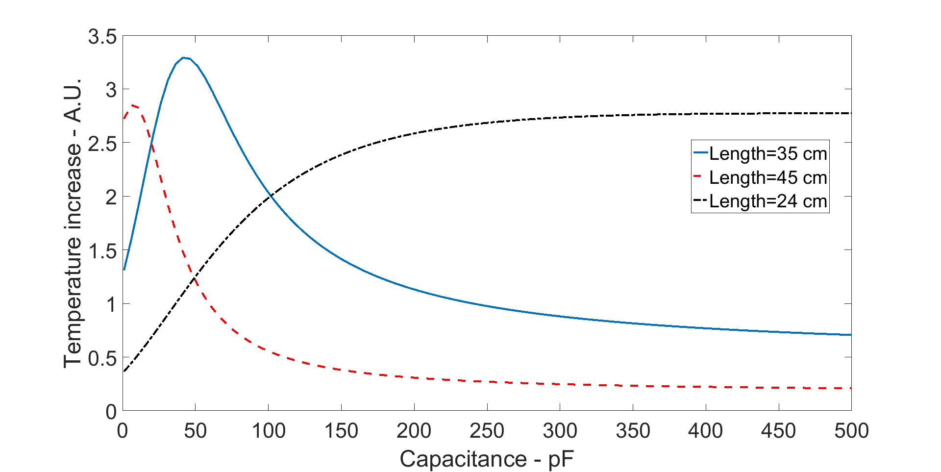
To show the effect of the connection impedance between the lead and the case, the tip temperature increase when there is no perfusion, was calculated for 3 different lead lengths by placing a capacitance between the lead and the case. The value of the capacitance was swept from 1pF to 500pF and the lead tip temperature was calculated inside the medium with relative permittivity of 65, conductivity of 0.2S/m at 63.795MHz. The wavenumber of the lead was 6.5-j1.62. The case circuit parameters from MoTLiM model, voltage source and an impedance, was Vc=5.9exp(j151)mV, Zc=0.9580-1.2879jΩ.
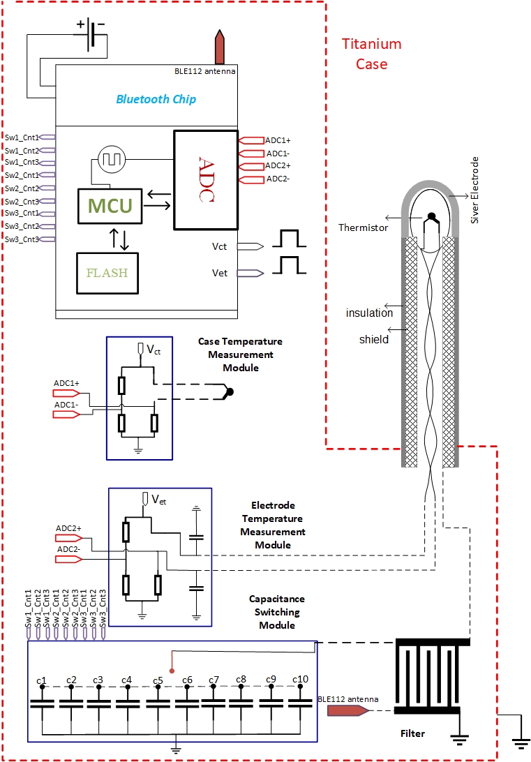
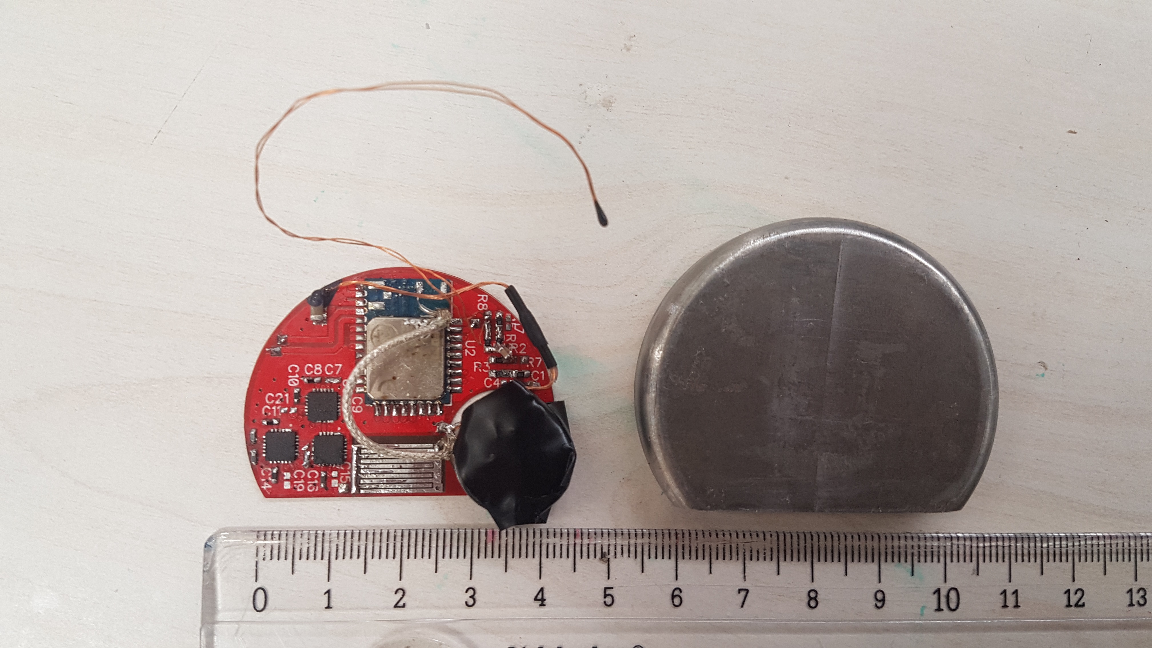
To demonstrate proposed system, we modified the previously presented Temperature Sensor Implant (TSI) system3 to switch between capacitor values for changing effective electrical length of the lead. The modified circuit block diagram is shown in Fig-1. The photograph of the circuit and the case is shown in Fig-2. To change the capacitance values, three 1-4 ultra-low power (110µA) RF switches (PE42442-Z, Peregrine Semiconductor, California, US) were placed. In total, 10-RF switchable capacitance nodes were designed and connected to input/output port of the Bluetooth chip (BLE112, Bluegiga Technologies, Espoo, Finland). These switch controls were wirelessly adjustable. Temperature measurement module, dimensions of the implant and connectivity were designed according to previous design3. The lead length was 45cm.
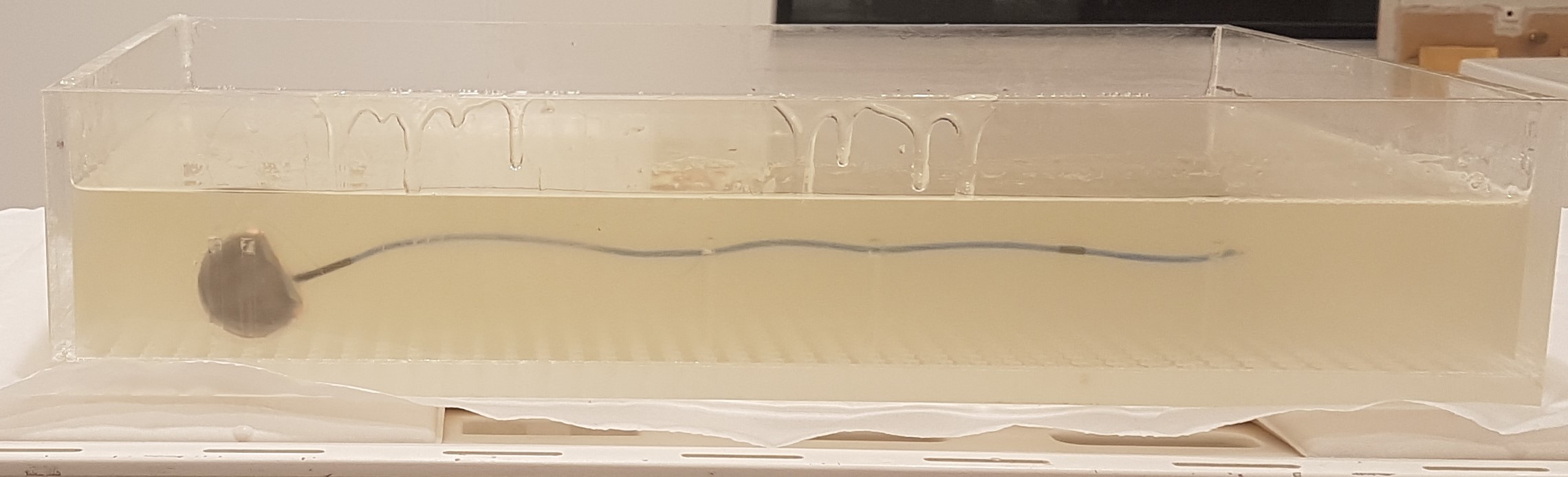
MRI experiment was performed on 1.5T scanner (Scimedix Inc., Incheon, South Korea). System’s body coil was used. A rectangular phantom (65x40cm) filled with hydroxyethylcellulose solution (14g/L with 1.5g/L NaCl, Total:29L) was used with RF only high SAR sequence (with scanner reported 4W/kg SAR, total time: 15-min). TSI was placed as shown in Fig-3, 4.5cm distant from the phantom edge. Before RF was applied to the phantom, impedance between the case and lead was switched to the open. Then, the sequence was started and the tip temperature was recorded for 325s. While the sequence was running the lead and the case connection was wirelessly changed to the short circuit and the tip temperature was recorded for another 265s. Then, the lead and the case connection was switched back to open circuit. The tip temperature transferred to the external computer wirelessly during the scanning.
Results
The calculations from MoTLiM model is shown in Fig-4 for lead lengths 24cm, 35cm and 45cm. Depending on the physical length of the lead increasing the capacitance value might either increase or decrease the temperature increase at the tip. In Fig-5, the tip temperature is shown during the scanning. The time points when the connection impedance was changed are marked with arrows. Tip temperature value decreased 5°C when the connection impedance switched from open to short circuit. It was also increased back when the connection impedance was switched back to open circuit.Discussion and Conclusion
We demonstrated a prototype system for wireless heating control of an AIMD during MRI. The system changes the connection impedance between the lead and the case. Two different case to lead connection impedance values were switched in this work as proof of a concept and tip temperature heating was changed during the scanning. Different conditions are investigating to understand practical challenges. Furthermore, the simulations indicate that temperature increase may not be decreased to zero heating, however; significant heating reduction can be achieved using this method. As a result, it can be useful for avoiding excessive heating if resonance condition occurs due to environmental factors inside human body and position inside the scanner.Acknowledgements
No acknowledgement found.References
- Acikel V, Atalar E. Modeling of radio-frequency induced currents on lead wires during MR imaging using a modified transmission line method. Med Phys 2011;38:6623–6632.
- Acikel V, Uslubas A, Atalar E. Modeling of electrodes and implantable pulse generator cases for the analysis of implant tip heating under MR imaging. Med Phys 2015;42:3922–3931.
- Silemek, B., Acikel, V., Oto, C., Alipour, A., Aykut, Z. G., Algin, O. and Atalar, E. (2017), A temperature sensor implant for active implantable medical devices for in vivo subacute heating tests under MRI. Magn. Reson. Med. doi:10.1002/mrm.26914
Figures