0640
SAR Calculations in Transmit-Only-Receive-Only RF systems: A Comparison of Detuning Methods for Rx Array Coils and their Implementation in EM SimulationsMatthias Malzacher1, Jorge Chacon-Caldera1, Mathias Davids1, and Lothar R. Schad1
1Computer Assisted Clinical Medicine,Medical Faculty Mannheim, Heidelberg University, Mannheim, Germany
Synopsis
The accurate simulation of SAR is important to guarantee patient safety in MRI measurements especially for local variations. Although most clinical RF systems are hybrid systems (separate Transmit (Tx) and Receive (Rx) coils), the effect of the Rx coils on Tx power consumption, B1+-homogeneity and SAR have been seldom investigated. Rx coils present highly conductive surfaces which affect the RF field distribution. In this work, we evaluate the performance of several detuning concepts and their realization in the EM simulations concerning Tx power consumption, B1+-homogeneity and SAR for a hybrid setup at 3T.
Introduction
The accurate simulation of specific absorption rate (SAR) is important to guarantee patient safety in MRI measurements especially for local variations since SAR in measurement only is monitored globally. Several studies have been presented to increase e.g. the accuracy of body models[1] or the variations of the RF excitation fields due to shimming[2]. However, although most clinical RF systems are hybrid systems (separate Transmit (Tx) and Receive (Rx) coils), the effect of the Rx coils on Tx power consumption, B1+-homogeneity and SAR have been seldom investigated[3-6]. Rx coils present highly conductive surfaces which affect the RF field distribution. Additionally, previous works which have taken Rx coils into account have not modeled the detuning as it is realized in state-of-the-art Rx arrays. In this work, we evaluate the performance of several detuning concepts and their realization in the EM simulations concerning Tx power consumption, B1+-homogeneity and SAR for a hybrid setup at 3T.Methods
EM fields were calculated using FEM simulations (CST–Computer Simulation Technology GmbH) with a tetrahedral mesh. Mesh refinement converged for all simulations to at least 5% for all S-parameters at the resonance frequency 123.2MHz.SAR was calculated using the power loss density after IEEE/IEC 62704-1, averaging mass 10g, normed to 1W accepted power. The SAR maps were normed afterwards to a mean B1+-field in the whole phantom of 11.7μT.
For excitation, a quadrature wide-bore BC coil was modeled (diameter=700mm,length=550mm,high-pass configuration with capacitors (5nF) in the legs representing PIN diodes for detuning).
A simplified head phantom was used which was comprised of a cylinder and a half-sphere (diameter=170 mm,length=225mm,material parameters: sigma=0.6 S/m,epsilon=54,Rho=1000kg/m³).
A 24-element Rx head coil was designed comprised of 3 rows (1st and 2nd row's coil diameter=130mm,3rd row's coil diameter=110 mm), with a conductor width=3mm, split 4 times for tuning capacitors and detuning network (see setup in Fig.1).
Five detuning concepts and their representation in the EM-simulations were used for the Rx array. The detuning network was applied at one gap of the coil representing the preamplifier port in every case.
Concept 1:
Adding a capacitor in series to the tuning capacitor (18pF) resulting in a higher resonance frequency. C small 1: resulting in 1.8pF. C small 2: resulting in 6pF.
Concept 2:
Adding a capacitor in parallel to the tuning capacitor (18pF) resulting in a lower resonance frequency. C big: resulting in 162pF.
Concept 3:
The Rx elements are built as closed loops[4].
Concept 4:
The Rx elements are opened at the preamplifier port realizing "ideal" detuning[1-3].
Concept 5:
Adding an inductor in parallel to the tuning capacitor creating a parallel resonance circuit at the resonance frequency. The detuning circuit was shunted by a resistor to adjust realistic detuning values (33dB,42dB,47dB).
Reference:
Tx coil only.
Results
Fig.2 shows the simulated E-fields in the middle sagittal plane normalized to 1W accepted power. E-Field distortions can be observed by all simulations including the Rx coils. Fig.3 displays the SAR ratios of the scaled SAR referred to the reference. Maximum SAR spots remained near the middle transversal plane on the edge of the phantom for all simulations except for Concept 3 (closed Rx coils). In this case, the spot of maximum SAR was shifted to the left edge. Concept 1 configurations revealed variations in SAR behavior depending on the inserted shift-capacitance whereas Concept 2 considerably influenced the SAR calculation. Concept 3 showed a reverse behavior compared to the other concepts. The open and detuned coils (Concept 4/5) showed similar behavior but influenced mean and maximum SAR within a range of 1% . Comparisons of power consumption, the maximum and mean SAR and the B1+-standard-deviation compared to the reference simulation values are shown in Fig.4. The Concept 1 configurations required less power but revealed higher standard-deviations in SAR and B1+ whereas Concept 2 yielded results out of the evaluated range. Closed loops (Concept 3) showed higher power requirements and decreased mean SAR but increased maximum SAR and B1+-standard-deviation. The results of the Concepts 4 and 5 were in the range of 10% compared to the reference.Discussion & Conclusion
This work reveals influences on power consumption, SAR and B1+-homogeneity by adding Rx arrays to the EM simulations. Several possibilities for modeling the detuned state of the Rx arrays were compared. The SAR differences regarding the reference simulations in a homogeneous phantom suggest that for accurate prediction of SAR and B1+-fields in complex human models and RF systems, the Rx configurations have to be taken into account. Moreover, the method for detuning the coils in simulation must be carefully matched to the one used in reality to assess SAR reliably.Acknowledgements
No acknowledgement found.References
[1] Wolf et al., SAR simulations for high‐field MRI: How much detail, effort, and accuracy is needed?. Magn. Reson. Med. 2013 ;69(4):1157-68.[2] Murbach et al., Pregnant women models analyzed for RF exposure and temperature increase in 3T RF shimmed birdcages. Magn. Reson. Med. 2017;77(5):2048-56.
[3] Wang et al., Numerical Investigation into Effects of a Receive Array on SAR in MRI, Proc. Intl. Soc. Mag. Reson. Med. 17, p.3102 (2009).
[4] Oh et al., Influence of a Receive-array Coil on Specific Absorption Rate at 3T: Simulations and Experiments with Basic Geometries, Proc. Intl. Soc. Mag. Reson. Med. 18, p.1444 (2010).
[5] Krishnamurthy et al., Effects of receive‐only inserts on specific absorption rate, B1+ field, and Tx coil performance. J. Magn. Reson. Im. 2014;39(2):475-84.
[6] Golestanirad et al., Feasibility of using linearly polarized rotating birdcage transmitters and close‐fitting receive arrays in MRI to reduce SAR in the vicinity of deep brain simulation implants. Magn. Reson. Med. 2017 ;77(4):1701-12.
Figures
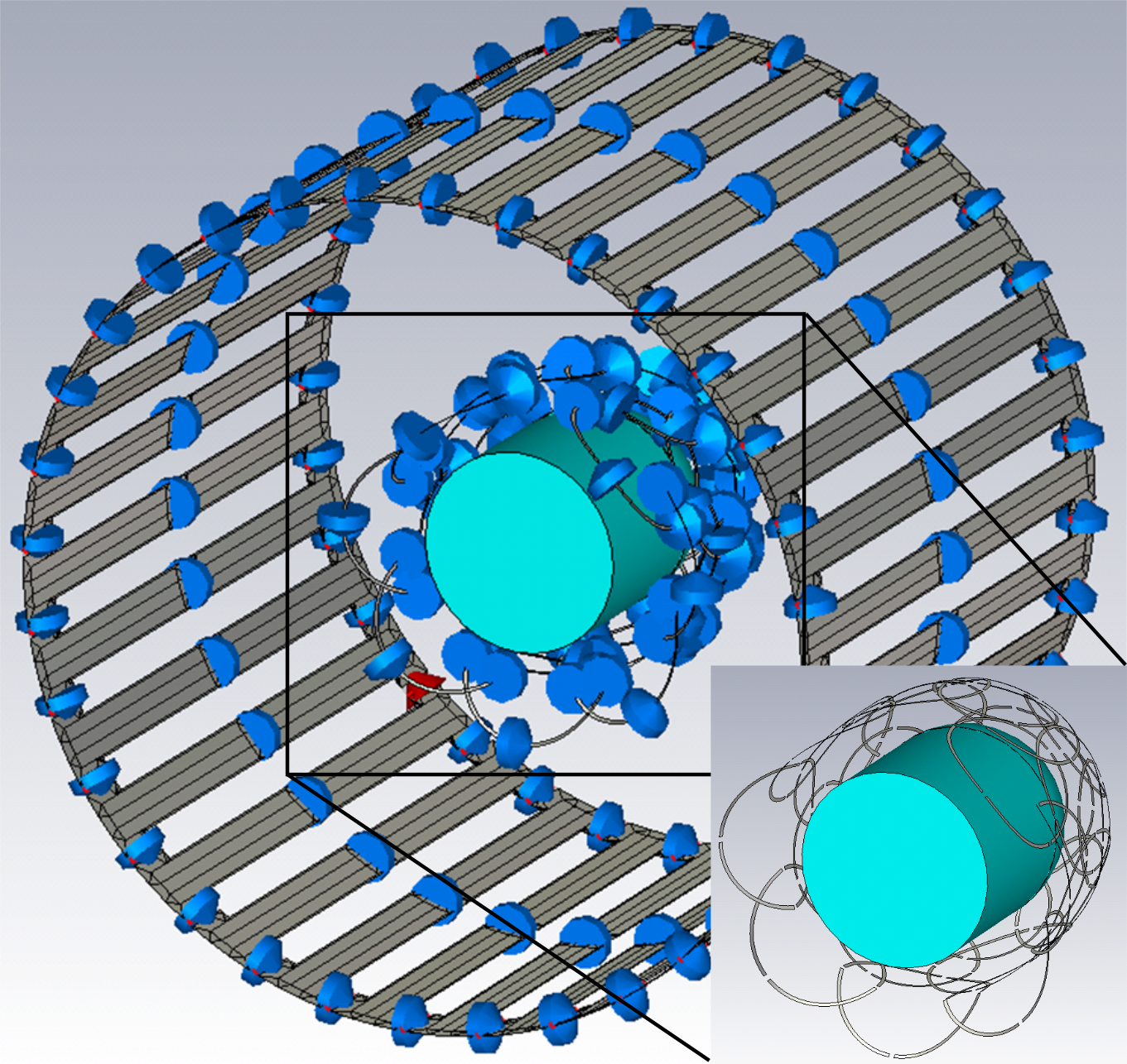
CST
simulation setup including the BC, the Rx head coil and the phantom.
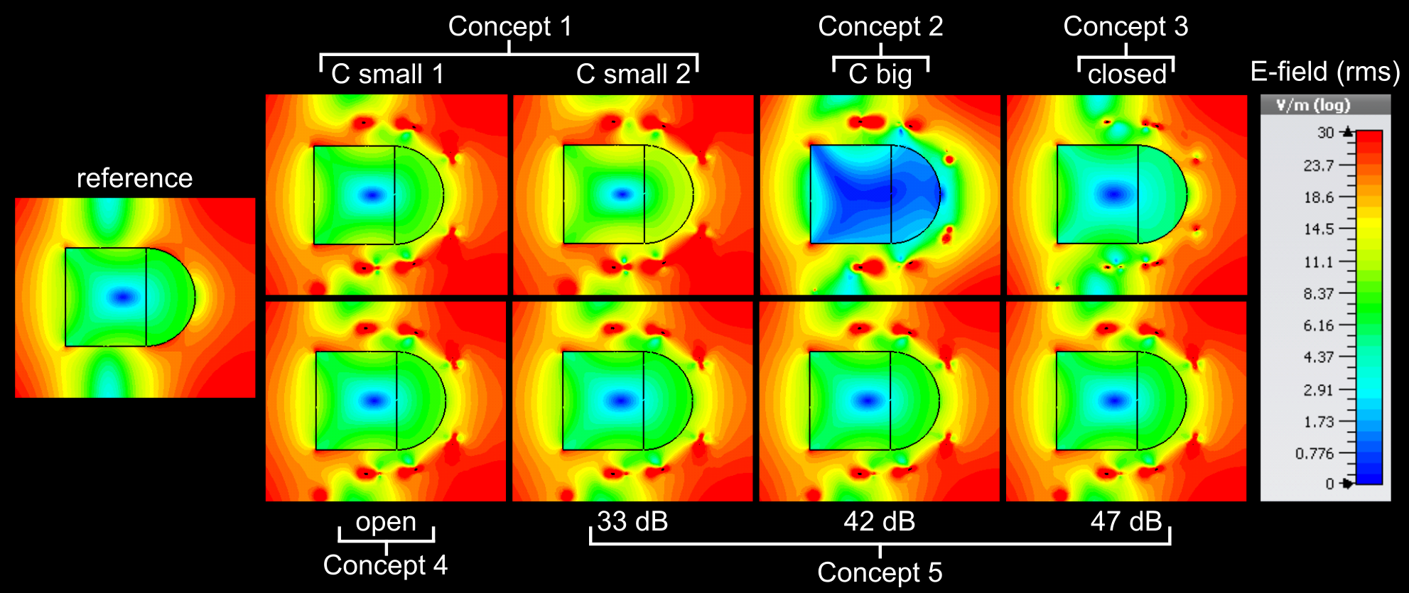
E-fields
(rms, logarithmic) in the middle sagittal plane of the different detuning concepts
and the reference simulation normalized to 1W accepted power.
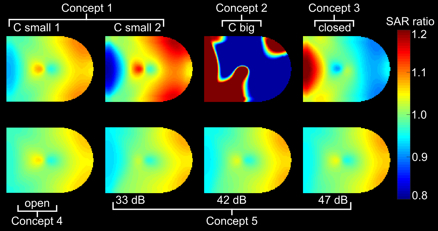
SAR
ratios in the middle sagittal plane of the different detuning setups referred
to the reference simulation.
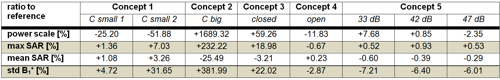
Results
of power consumption, SAR and B1+-homogeneity compared to
the reference simulation.