0639
Electrical lengthening to improve electromagnetic simulations and SAR calculations of meandered body dipole elements at 7T1Sir Peter Mansfield Imaging Centre, University of Nottingham, Nottingham, United Kingdom, 2National Institute for Health Research (NIHR) Nottingham Biomedical Research Centre, Nottingham University Hospitals NHS Trust, University of Nottingham, Nottingham, United Kingdom
Synopsis
This study investigated the use of electrical-lengthening as an alternative method of simulating meandered dipole arrays. Dipoles were compared with (a) differing inductor positions, (b) rotating dipole along main axis and (c) for multiple dipole transmission. Results showed a simple single wire dipole model with electrical-lengthening produced comparable SAR solutions, were less effected by rotations and cut simulation times by up to 10 times.
Introduction
Body scanning at 7T provides significant improvements compared with lower fields and parallel transmit (ptx) dipole antenna have numerous advantages [1, 2]. It is essential that accurate SAR models can be obtained to set suitable power safety limits [3], requiring numerical simulations that rely heavily on well-resolved discretization of modelled systems.
Body dipole arrays typically include meanders to tune at the correct resonant frequency [4] which prove difficult to mesh in Cartesian gridding systems typically used in simulation software. Meanders that are angled to the Cartesian grid planes result in ‘staircase’ meshing which can affect simulated RF tuning. The extra meshing required also results in computationally intensive simulations. Alternatively, inductors can provide ‘electrical-lengthening’ to strip-line dipoles. Whilst B1+ field and SAR may differ for these two arrangements close to the coil, at distances used in MRI scanning these are likely to be small. This study investigated the use of electrical-lengthening as an alternative method of simulating meandered dipole arrays.
Methods
Comparisons of meandered vs electrically-lengthened dipoles were made using numerical simulations (Remcom XFdtd v7.5.0.3). A simple cylindrical muscle phantom (ρ=1090 kg/m3, σ=0.8 S/m) was modelled (length=56 cm,radius =200mm). A meandered dipole model was created (figure 1) based on the physical dimensions of MR Coil’s (Utrecht, The Netherlands) 8 transmit element body coil (length=31cm,4x meanders). For comparisons, a number of electrically-lengthened single wire dipoles were created as outlined below. Elements were modelled as perfect conductors, and Cartesian ‘PrOGrid’ Optimized gridding was used to improve gridding (20vs10 cells across for good vs poor conductors respectively). In each case of electrical-lengthening, S-Parameter tests were run and inductors adjusted to tune to ~298MHz, and then steady state simulations were run at this discrete frequency (driven at 1W). B1+ and 10g averaged SAR we determined and reported. Meandered vs electrical-lengthened dipoles were compared in the following conditions:
(a) Varying inductor position along dipole (2 inductors equi-distant either side of drive at 2,5,10 and 20 mm, convergence criteria -30 dB used). Subsequent inductor models only simulated 2x75nH inductor 2mm either side of drive.
(b) Varying angle about dipole’s main axis (0,20,40,60,80 and 90 degrees from Cartesian grid planes, convergence -5 dB)
(c) Multiple dipoles separated as intypical in vivo set-ups(modelled along Cartesian planes for good tuning, 1, 2 and 4 adjacent dipoles). In the 4 dipole model a reduced gridding regime was required due to lack of memory.
Results
Inductor position. Figure 2 shows the max SAR values of each model. Figure 3 compares B1+ profiles through the centre of the tissue (above the feed) showing close agreement between models.
Rotation of dipole. Simulation times for the meandered model were 35, 21, 15, 10, 11, 35 minutes (RAM required: 437,420,511,452,395,440 MB) for 0,20,40,60,80 and 90 degrees respectively. Only models running parallel to planes tuned close to resonance (360 MHz, figure 4). Models rotated off plane tuned at 900,1150,1150,940 MHz for 20,40,60 and 80 degrees respectively. Simulation times for the electrically-lengthened model were 4,5,6,7,6,4 minutes (RAM required: 199,202,215,219,210,199 MB) and tuned at 295,294,290,287,300,295 for 0,20,40,60,80,90 degrees respectively.
Multiple dipoles. Figure 5 shows SAR results for multiple dipoles. Simulation times were 1h20m and 47m (RAM required:1.2 GB and 943 MB with reduced gridding) and 9m and 13m (RAM required:340 and 463 MB) for the 2 and 4 dipole model models respectively.
Discussion
Accurate SAR modelling is crucial for safe MRI scanning at 7T. However, this is time consuming, computationally demanding and often relies on Cartesian gridding. Non-Cartesian gridding methods increase the simulation demand further, which is especially the case for meandered dipoles.
This study has demonstrated that electrical-lengthening offers significant advantages. Tuning remained constant for all angles and extra gridding was not required so mesh sizes were greatly reduced with less memory required (up to 4x less). Convergence was also found much quicker due to use of single electrical paths resulting in 10x reduction in computational time. The B1+ and SAR profiles showed good agreement between models. Of interest, the meandered model showed a reduce peak 10g SAR compared with the inductor model when 4 dipoles were run together. This result was obtained with a reduced gridding regime in the meandered case due to memory limitations. Furthermore, given the results in the 1 and 2 dipole models, a greater SAR value is expected which may lead to the conclusion that the inductor model is providing a more accurate solution. Further work should explore this.
Conclusion
Use of electrically lengthened models provide a faster and less computationally intensive method of simulating SAR generated from physically meandered dipoles whilst also improving the tuning at angles off Cartesian planes allowing for accurate coil positioning in modelling.Acknowledgements
No acknowledgement found.References
1. Raaijmakers, A.J.E., P.R. Luijten, and C.A.T. van den Berg, Dipole antennas for ultrahigh-field body imaging: a comparison with loop coils. Nmr in Biomedicine, 2016. 29(9): p. 1122-1130.
2. Padormo, F., et al., Parallel transmission for ultrahigh-field imaging. Nmr in Biomedicine, 2016. 29(9): p. 1145-1161.
3. Graesslin, I., et al., A specific absorption rate prediction concept for parallel transmission MR. Magnetic Resonance in Medicine, 2012. 68(5): p. 1664-1674.
4. Raaijmakers, A.J.E., et al., The fractionated dipole antenna: A new antenna for body imaging at 7 Tesla. Magnetic Resonance in Medicine, 2016. 75(3): p. 1366-1374.
Figures
XFdtd models of (a) single dipole close to cylindrical muscle phantom (b) meandered dipole and (c) single wire dipole with 2 inductors each 2 mm from the centre drive (each 75 nH ).
Underneath illustrates the effects of moving meanders off cartesian planes with ‘staircase’ meshing required.
Electromagnetic XFdtd simulated solution of (a) B1+ and (b) SAR in single dipole for standard meandered model (left) and electrically-lengthened inductor model (right). The increased meshing required for meandered models can also be seen in the gridding overlayed.
Inductor models are single wire dipoles with a centre drive, and were simulated with 2 inductors (adjusted for tuning) at varying distances either side of the feed. (c) shows the effects on SAR of inductor position (distances on legend are either side of centred drive)
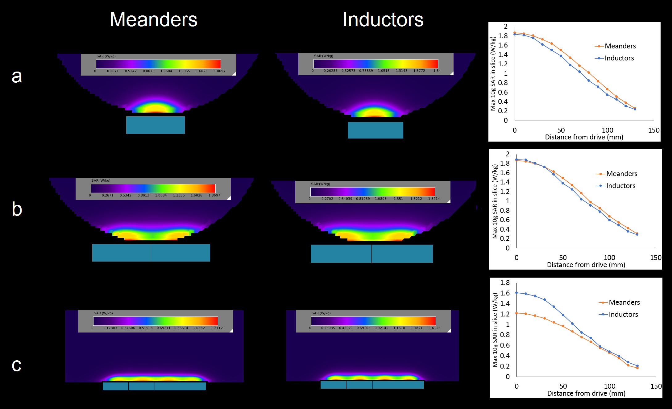
SAR profile in centre slice of 1, 2 and 4 dipole models (a, b and c respectively) for meandered (left) and electrically-lengthened models (right).
Also max 10g SAR per slice is plotted alongside to illustrate the difference between meandered and electrically-lengthened models.