0505
A Weighted Head Accelerator Mechanism (WHAM) for imaging brain tissue deformation during mild head rotation using a tagged MRI sequence1Imaging Research Center/Radiology, Cincinnati Children's Hospital Medical Center, Cincinnati, OH 45229, Cincinnati, OH, United States, 2Radiology, Nationwide Children's Hospital, Columbus, OH, United States, 3Division of Sports Medicine, Cincinnati Children's Hospital Medical Center, Cincinnati, OH, United States, 4Department of Physics, University of Cincinnati, Cincinnati, OH, United States, 5Department of Biomedical Engineering, University of Cincinnati, Cincinnati, OH, United States
Synopsis
A new research tool, the Weighted Head Accelerator Mechanism (WHAM), is described. The WHAM, used together with a custom MRI sequence, permits in depth investigations into brain biomechanics during mild head rotations and the evaluation of mild traumatic brain injury mitigating strategies by directly evaluating their effects on brain biomechanics in vivo.
Introduction:
Mild traumatic brain injury (mTBI) is a significant public health problem1. The Centers for Disease Control and Prevention estimates the annual incidence of sports and recreation-related mTBI in the United States to be between 1.6 and 3.8 million with an annual cost of well over $75 billion2.
We constructed an apparatus, Weighted Head Accelerator Mechanism (WHAM), to directly visualize the deceleration, deformation, and recoil of the brain parenchyma with a temporal resolution of 2.56 ms, allowing element-wise calculation of the strain and shear forces experienced by the brain in vivo. Our apparatus represents an enhancement of existing head rotation devices3-4 in that it allows imaging axial head rotation of any arbitrary velocity, acceleration, rotation direction, or starting/ending position with an impulse/acceleration at either the beginning or end of the rotation.Methods:
Operation: The WHAM (Fig 1A) is designed for use in 70 cm bore magnets. WHAM operation is described with reference to Fig 1B. The front shaft has a rotation limiter, restoration pulley and an anvil disk. The rear shaft is composed a rotation limiter, drive pulley, trigger disk, and hammer disk. An activation or “drop” of the WHAM occurs when a pin is retracted, releasing the trigger disk. The rear shaft, now free to rotate, accelerates driven by a “drop” weight (DW) attached to the drive pulley. An impulse is delivered to the head holder when the hammer of the rear shaft strikes the anvil of the front shaft causing rotation of the head holder. An optical sensor sends a TTL pulse to serve as an external trigger for the scanner. Following each drop, an operator resets the WHAM by rotating the trigger disk back to its starting position. A weight (RW) attached to the restoration pulley returns the head holder back to its starting position. Each drop of the WHAM provides highly reproducible motion permitting data acquisition over a series of drops (i.e. acquiring a fraction of k-space for each frame during each drop, filling k-space in a series of drops).
Calibration: To ensure operation of the WHAM is within safe physiologic limits, the head holder was imaged with a high speed camera (1000 frames/sec) during operation of the WHAM with various combinations of weights and hammer-anvil separations. Angular velocities and accelerations experienced by the head holder were calculated by frame-by-frame analysis of the image data.
Imaging Acquisition Protocol: Scans were performed on a 3T Philips Ingenia scanner equipped with a 12-channel head coil. Scanning was performed using the vendor's standard cardiac MRI functionality capable of acquiring data at multiple "phases" following a single trigger event. The WHAM TTL pulse was used as the external trigger rather than an ECG waveform. After a trigger event, a 2D SPAMM tagging grid is applied followed by imaging using a spoiled gradient echo acquisition. Each k-space line is acquired at 256 temporal phases. The WHAM mechanism is then reset and the process is repeated to fill additional lines of k-space.
Sequence parameters are: FOV = 220 x 220 mm, resolution = 1.34 mm (read) x 2 mm (phase), 8 mm slice, partial Fourier 0.75, SENSE 3, TRTE = 2.5/0.75 ms, flip angle 4°, bandwidth = 1105 Hz/pixel. To minimize TR, partial-echo was enabled in the readout direction. These settings allowed for only 28 repetitions of the head motion to build a 2D image (i.e. only 28 of 110 k-space lines were acquired). Images were reconstructed at a resolution of 0.98 x 0.98 mm. The tagging grid had an 8 mm tag spacing along each axis.
Motion analysis: Bulk rotation was removed by rigid coregistration using the fMRIB linear image registration tool (FLIRT)5-6. Local displacements relative to a pre-motion reference frame were determined using the harmonic phase (HARP) techinque7. HARP produces complex-valued images whose phase is linearly related to spatial displacement. Phase isocontours were determined using the marching squares algorithm8 as implemented in scikit-image9.
Results:
Analysis of the calibration data indicates the WHAM configurations used in this study are safe and within the AIS = 0 zone on the Abbreviated Injury Scale10. Fig. 2 shows representative images after rigid coregistration. Fig. 3 shows the isocontours for the three timepoints used in Fig. 2. Fig. 4 shows a quantitative map of non-rigid deformation relative to the first frame of the timecourse shown in Fig. 2.Conclusion:
The WHAM represents a new research tool, previously unavailable, allowing in depth investigations into brain biomechanics and the evaluation of mTBI mitigating strategies by directly evaluating their effects on brain biomechanics in vivo.
Acknowledgements
No acknowledgement found.References
1. Marar M, McIlvain NM, Fields SK, et al. Epidemiology of concussions among United States high school athletes in 20 sports. The American journal of sports medicine, 40:747-755, 2012.
2. CDC. Heads up; facts for physicians about mild traumatic injury (mTBI). In: Prevention CfDCa, ed.; 2013.
3. Sabet AA, Christoforou E, Zatlin B, Genin G, Bayly PV. Deformation of the human brain by mild angular head acceleration. J Biomech 41, 307 – 315, 2008.
4. Knutsen AK, Magrath E, McEntee Julie, et al. Improved measurement of brain deformation during mild head acceleration using a novel tagged MRI sequence. J Biomech 47(14), 3475-3481, 2014.
5. Jenkinson M, Smith SM. A Global Optimisation Method for Robust Affine Registration of Brain Images. Medical Image Analysis, 5(2), 143-156, 2001.
6. Jenkinson M, Bannister P, Brady JM, Smith SM. Improved Optimisation for the Robust and Accurate Linear Registration and Motion Correction of Brain Images. NeuroImage, 17(2), 825-841, 2002.
7. Osman NF, McVeigh E.R. , Prince JL. Imaging Heart Motion Using Harmonic Phase MRI. IEEE Trans. Medical Imaging, 19(3):186-202, 2000
8. Lorensen, William and Harvey E. Cline. Marching Cubes: A High Resolution 3D Surface Construction Algorithm. Computer Graphics (SIGGRAPH 87 Proceedings) 21(4) July, p. 163-170, July 1987.
9. Stéfan van der Walt, Johannes L. Schönberger, Juan Nunez-Iglesias, François Boulogne, Joshua D. Warner, Neil Yager, Emmanuelle Gouillart, Tony Yu and the scikit-image contributors. scikit-image: Image processing in Python. PeerJ 2:e453 ,2014 .http://dx.doi.org/10.7717/peerj.453
10. Duma S. and Rowson S. The Biomechanics of Concussion: 60 Years of Experimental Research. In: Concussions in Athletics: From Brain to Behavior, Springer New York, p. 115-137, 2014.Figures
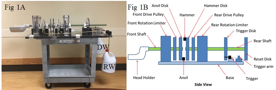
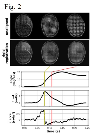
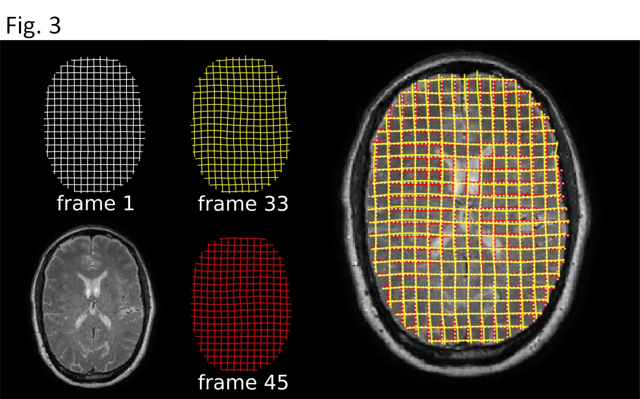
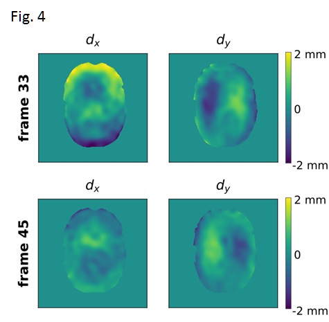
Fig. 4 Quantitative maps of non-rigid brain deformation relative to the first frame of the timecourse. The x and y components of the displacement are displayed separately.